
Views: 0 Author: Site Editor Publish Time: 2026-09-16 Origin: Site


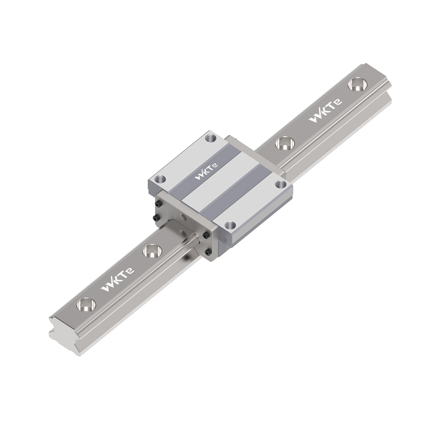
Precision motion control in industrial automation hinges on a single mechanical objective: moving heavy payloads in a perfectly straight line while minimizing friction. At its core, a Linear guide rail adapts the proven, low-friction principles of rotary bearings into a linear format, solving complex engineering challenges related to load support and motion precision. Specifying the wrong linear motion component results in system deflection, premature bearing failure, excessive maintenance downtime, and compromised machining or automation accuracy. Furthermore, inadequate guides fail to protect expensive drive mechanisms, like ball screws or actuators, from damaging side loads. Understanding the internal mechanics of a linear guide rail is not just an academic exercise; it is the baseline requirement for evaluating load capacities, calculating structural rigidity, and selecting the correct rail profile for a specific operating environment.
Friction Conversion: A linear guide rail system functions by converting high-friction sliding motion into low-friction rolling motion via recirculating elements (balls or rollers) trapped between a carriage and a fixed rail.
Load Distribution: The geometric design of the rail’s raceways (such as a "V" groove or circular arc) maximizes surface contact area, dictating how the system absorbs multi-directional forces, including downward, upward, and moment loads (pitch, yaw, and roll).
Selection Trade-offs: Choosing between ball-type and roller-type linear guides requires balancing speed requirements against load capacity; point-contact balls excel at high speeds, while line-contact rollers provide superior rigidity for heavy-duty machining.
Implementation Criticality: Even the highest-rated linear guide rail will fail prematurely if mounting surface tolerances, alignment procedures, and environmental sealing protocols are not strictly followed.
The fixed rail establishes the fundamental X, Y, or Z axis for any automated system. It provides a highly rigid foundation capable of supporting substantial moving loads without deflection. Running along the length of this rail are precision-ground raceways. These grooves serve as the exact track for the rolling elements. Manufacturers typically construct these rails from high-carbon bearing steel or stainless steel to withstand constant mechanical stress.
To prevent premature wear, the raceways undergo induction hardening. This thermal process creates a hardened outer shell, usually reaching 58 to 62 HRC on the Rockwell scale, while maintaining a ductile core to absorb impact forces. The depth of this hardened case dictates the rail's ability to resist point-loading from the bearings. Mounting holes are precisely drilled and counterbored along the rail. This allows bolt heads to sit flush below the top surface, avoiding any interference with the moving carriage above.
The carriage acts as the primary load-bearing interface connecting the moving machinery to the stationary rail. Internally, the carriage architecture is divided into specific functional zones. The load zone is where the rolling elements make direct contact with both the carriage and the rail, actively supporting the payload. The non-load zone includes the return path where bearings circulate freely without bearing weight.
The physical housing of the carriage contains these internal channels, keeping the rolling elements aligned and protected from external debris. Carriages come in various mounting styles to accommodate different machine designs. Flanged blocks offer a wider mounting surface for heavy top-down or bottom-up bolting. Narrow blocks fit into compact spaces where width is restricted. The carriage body is typically machined from alloy steel, though aluminum versions exist for low-weight, low-load applications.
Steel body housing the internal raceways and return tubes.
Synthetic resin end caps that guide the bearings through the 180-degree turn.
Bottom and side seals to retain grease and exclude contaminants.
Grease nipple or lubrication port for maintenance access.
Rolling elements bridge the physical gap between the carriage and the rail, enabling smooth motion. The choice between balls and rollers fundamentally changes the performance characteristics of the system.
Spherical balls utilize point contact. They touch the raceway at a very small, concentrated area. This design minimizes friction, allowing for rapid acceleration, low heat generation, and high-speed operation. Cylindrical rollers utilize line contact, distributing the load across a much wider surface area. This line contact provides superior structural rigidity and massive load-carrying capacity. Roller guides typically sacrifice top-end speed due to increased rolling resistance and higher internal friction.
Feature |
Ball-Type Guide |
Roller-Type Guide |
|---|---|---|
Contact Type |
Point Contact |
Line Contact |
Friction Level |
Very Low |
Moderate |
Load Capacity |
Standard to High |
Ultra-High |
Rigidity |
Moderate |
Maximum |
Max Speed |
Up to 5 m/s |
Up to 3 m/s |
Primary Application |
Automation, Packaging |
CNC Machining, Heavy Presses |
Continuous linear motion requires a closed-loop path for the bearings. Without it, the rolling elements would simply fall out at the end of the carriage stroke. The recirculation system solves this mechanical problem. Rolling elements enter the active load zone, traveling along the raceway under pressure.
As they reach the end of the carriage, they enter a specialized synthetic end cap that redirects them 180 degrees. They then travel back through a hollow return tube or channel integrated into the carriage body. Finally, another end cap feeds them back into the load zone, creating an infinite loop of low-friction movement. The design of these return paths heavily influences the maximum speed and noise level of the guide. Smoother transitions inside the end caps reduce bearing impact and extend the component's life.
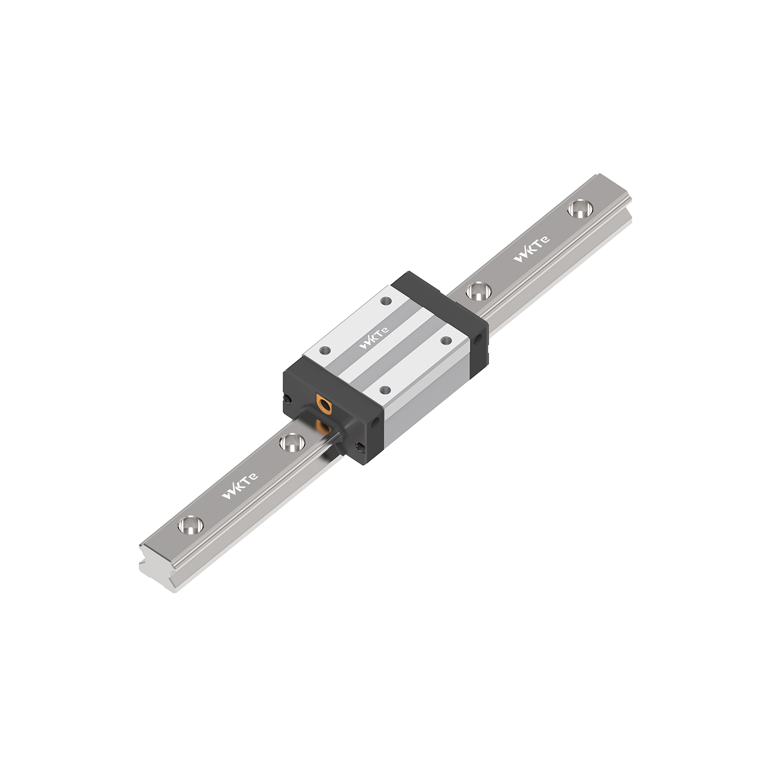
Traditional sliding surfaces generate immense kinetic friction, requiring massive motor torque to initiate and maintain movement. A Linear guide rail eliminates this inefficiency by substituting sliding friction with rolling resistance. Because rolling elements circulate between the rail and carriage, the coefficient of friction drops dramatically. A standard sliding dovetail way might have a friction coefficient of 0.1 to 0.2. A rolling linear guide operates at roughly 0.002 to 0.003.
This mechanical conversion allows motors to move massive payloads with minimal effort. It significantly improves overall energy efficiency and reduces heat generation. More importantly, it eliminates the stick-slip phenomenon. Stick-slip occurs when static friction exceeds kinetic friction, causing jerky movements at low speeds. By removing this barrier, rolling guides enable sub-micron positioning accuracy for precision manufacturing.
The shape of the raceway groove dictates how effectively the system handles weight. Flat surfaces offer poor load distribution and high stress concentrations. Instead, manufacturers utilize "V" groove (Gothic arch) or circular arc raceway designs. These specific profiles wrap around the rolling balls, vastly increasing the surface contact area compared to a flat track.
The Gothic arch design creates a four-point contact scenario, allowing a single row of balls to handle loads from multiple directions. A standard 45-degree contact angle is frequently employed in these designs. This specific geometry allows the guide to carry equal load capacities in all four primary directions: radial (downward), reverse-radial (upward), and lateral (side-to-side). This equal load rating simplifies machine design, as engineers do not need to derate the guide based on its mounting orientation.
In real-world applications, payloads are rarely perfectly centered over the carriage. Overhanging loads or offset cutting forces generate moment loads, which attempt to twist or rotate the carriage off the rail. The system's ability to resist these forces depends heavily on the spacing of the internal rolling elements and the overall length of the carriage.
Longer carriages with widely spaced bearing tracks provide superior leverage against moment loads, preventing deflection and maintaining structural rigidity under heavy dynamic forces. When designing a system with high moment loads, engineers often use two parallel rails with two carriages per rail. This configuration converts moment loads back into standard radial and lateral loads, which the guides handle much more efficiently.
Moment Load Type |
Axis of Rotation |
Common Cause in Machinery |
|---|---|---|
Pitch |
X-Axis (Tilting forward/back) |
Rapid acceleration of a tall, top-heavy payload. |
Yaw |
Y-Axis (Twisting left/right) |
Offset drive mechanisms or asymmetrical cutting forces. |
Roll |
Z-Axis (Tilting side-to-side) |
Cantilevered loads hanging off the side of the carriage. |
Preload is the intentional introduction of internal negative clearance within the carriage. Engineers achieve this by inserting rolling elements that are microscopically larger than the available space between the raceways. This eliminates mechanical backlash and dramatically increases system rigidity. Applying preload compresses the rolling elements slightly, meaning they require more force to deform further under an external load.
Heavy preload (often designated as Z3 or ZB) is mandatory for heavy-duty CNC machining centers. It prevents tool chatter and maintains tight tolerances during aggressive cutting operations.
Normal or zero preload (Z0) is ideal for packaging equipment or automated storage systems. In these applications, maximum speed and low friction take priority over extreme rigidity.
Light preload (Z1 or ZA) offers a middle ground. It suits general automation tasks requiring moderate precision without excessive rolling resistance.
Evaluating a linear guide requires understanding two primary metrics. The Basic Static Load Rating (C0) defines the maximum load the system can handle before permanent plastic deformation occurs on the raceway or rolling elements. Exceeding this value causes brinelling, ruining the guide instantly. The Basic Dynamic Load Rating (C) is used to calculate the operational lifespan under moving conditions.
Engineers use the L10 life calculation formula. This formula incorporates the dynamic load rating, the actual applied payload, operating speed, and duty cycle. For ball-type guides, the formula is L = (C/P)^3 * 50km, where P is the equivalent dynamic load. This predicts the distance the guide will travel before 10% of a given batch of bearings shows signs of material fatigue. Calculating this allows maintenance teams to schedule replacements before catastrophic failure occurs.
Determine the mass and center of gravity of the payload.
Calculate the dynamic forces applied during maximum acceleration and deceleration.
Identify all moment loads based on the payload's offset from the carriage center.
Calculate the equivalent dynamic load (P) combining all radial, reverse-radial, and lateral forces.
Apply the L10 formula to determine the expected travel life in kilometers.
Mechanical bottlenecks restrict maximum operating speeds. The primary limitation is the impact force generated when rolling elements exit the load zone and strike the end caps during recirculation. At extreme velocities, these collisions cause excessive noise, heat buildup, and eventual component failure. Standard ball guides typically max out around 3 to 5 meters per second.
To push speed limits higher, manufacturers utilize ball spacers or caged ball technology. These synthetic cages separate individual balls, preventing bearing-to-bearing friction. When balls rub against each other, they rotate in opposite directions at the contact point, generating significant friction and heat. Cages eliminate this issue. This reduces operational noise, retains lubrication better, and allows for significantly higher maximum allowable speeds without destroying the end caps.
Selecting the correct architecture depends entirely on the operational environment and mechanical demands. A mismatch here guarantees poor performance and short component life.
Heavy Industry and Machine Tools: Roller-type guides with heavy preload are mandatory for milling and turning centers. Their unmatched rigidity and line-contact load distribution handle the violent vibrations of metal cutting.
Semiconductor and Medical Devices: Cleanroom compliance requires miniature, stainless steel linear guides equipped with caged balls. These ensure low particulate generation, smooth operation, and resistance to harsh chemical washdowns.
Packaging and Automation: Standard ball-type guides are highly effective for high-speed, repetitive pick-and-place operations. Rapid acceleration is more critical than extreme load capacity in these scenarios.
A linear guide system is only as accurate as the surface to which it is bolted. If the machine bed is warped, the guide rail will conform to that distortion when torqued down, destroying the intended precision. Strict adherence to surface flatness and parallelism tolerances is non-negotiable. Machine bases must be milled or ground to match the accuracy class of the guide rail.
Engineers must utilize machined reference edges on the machine base to ensure the rail is installed perfectly straight. The master rail is pushed against this reference edge and torqued to specification. The secondary rail is then aligned parallel to the master. Failure to align parallel rails correctly will cause the carriages to bind. This drastically increases internal friction, overloads the bearings, and causes premature system failure.
Clean the mounting surface and the bottom of the rail with a precision solvent.
Place the master rail against the machined reference edge on the machine bed.
Insert mounting bolts and tighten them lightly.
Use a lateral push block to press the rail firmly against the reference edge, then torque the bolts to the manufacturer's specification starting from the center and moving outward.
Mount the secondary rail, leaving bolts slightly loose.
Install the carriages and the machine table, then stroke the table back and forth to naturally align the secondary rail before final torquing.
The ingress of metal shavings, abrasive dust, or chemical coolant will rapidly destroy precision-ground raceways. Protecting the internal rolling elements is critical for longevity. Engineers must evaluate and specify appropriate sealing systems based on the operating environment. Standard end seals provide basic dust protection for clean factory environments.
In harsher conditions, side seals prevent debris from entering underneath the carriage. Double seals are used for highly contaminated areas like woodworking or grinding. In environments with heavy metal chips or welding spatter, synthetic seals will melt or tear. Here, metal scrapers are required to physically shear debris off the rail surface. External protective bellows or telescopic steel covers offer the ultimate protection, completely enclosing the rail and carriage assembly.
Sealing Option |
Primary Function |
Best Operating Environment |
|---|---|---|
Standard End Seal |
Keeps grease in, light dust out. |
Cleanrooms, electronics assembly. |
Double End Seals |
Enhanced barrier against fine particulates. |
Woodworking, fiberglass routing. |
Bottom/Side Seals |
Prevents upward ingress of contaminants. |
Inverted mounting, general automation. |
Metal Scraper |
Shears hot or sharp debris off the rail. |
Welding, heavy metal machining. |
Lubrication forms a microscopic hydrodynamic film that separates the rolling elements from the steel raceway, preventing metal-to-metal contact. Without this film, the guide will destroy itself in a matter of hours. Lithium soap-based greases are standard for general applications. Manual grease fittings are common for standard automation, but automated grease or oil lubrication systems are preferred for continuous, high-speed operations.
The stroke length of the application directly impacts lubrication distribution. Short-stroke applications, where the carriage moves less than its own length, often fail to distribute grease evenly across the entire load zone. This requires specific low-viscosity lubricants or programmed maintenance cycles. Operators must periodically run the carriage through its full stroke to redistribute the grease and rebuild the protective film.
Brinelling refers to the permanent plastic deformation of the raceway surface. It appears as microscopic dents matching the exact shape and spacing of the rolling elements. This occurs when the system experiences shock loads, impacts, or static overloads that exceed the Basic Static Load Rating (C0). Dropping a heavy payload onto the machine table is a common cause.
Once brinelling occurs, the carriage will vibrate, run rough, and quickly degrade as the bearings roll over the dents. Mitigation requires proper initial sizing to account for dynamic impact forces. Engineers must calculate the maximum possible shock load, not just the resting weight. Additionally, integrating external shock absorbers, hard stops, or dampening materials at the ends of the travel stroke prevents hard crashes and protects the internal mechanics.
Fretting corrosion is a specific wear phenomenon common in applications with very short, rapid strokes, such as vibration testing equipment or short-stroke actuators. Because the carriage does not travel far enough to complete a full recirculation cycle, the lubrication film cannot form properly. The bearings rub back and forth in the exact same spot.
This leads to localized metal-to-metal friction, oxidation, and rapid raceway degradation. It is often visible as a reddish-brown powder bleeding from the carriage seals. To mitigate fretting, engineers must specify specialized anti-fretting greases designed for micro-oscillations. Programming periodic full-stroke movements into the machine cycle also allows the carriage to redistribute lubrication effectively and sweep away oxidized particles.
When two parallel rails are installed out of alignment, the carriages are forced to absorb unintended lateral loads. They constantly fight each other as they move down the track. This uneven loading causes intense stress concentrations on specific rows of rolling elements, leading to rapid flaking or spalling of the raceway surface. The steel literally peels away under the extreme pressure.
Mitigation starts with improving the machining tolerances of the base structure and using dial indicators during installation to verify parallelism. If perfect alignment is impossible due to structural limitations, utilizing self-aligning carriage designs can help. Some manufacturers offer carriages with slight internal compliance to absorb minor mounting discrepancies without transferring destructive stress to the internal bearings.
Calculate your application's specific static, dynamic, and moment load requirements before reviewing manufacturer catalogs.
Consult L10 life charts to verify that the chosen component will meet the required operational lifespan under your specific duty cycle.
Request detailed CAD models to verify mounting dimensions, carriage clearances, and reference edge requirements prior to finalizing the machine design.
Specify appropriate sealing and lubrication accessories based on the exact environmental hazards of your production floor to prevent premature contamination failure.
A: A linear shaft uses round rods and linear bushings, suitable for lighter loads and moderate precision. A profiled linear guide uses a machined rail with specific raceway grooves, offering significantly higher load capacities, rigidity, and the ability to handle heavy moment loads in all directions.
A: Sizing requires calculating the maximum applied payload, dynamic forces during acceleration, and moment loads. These figures are compared against the manufacturer's static and dynamic load ratings. You must also factor in the required operational lifespan using the L10 life calculation formula.
A: Yes. Due to their internal raceway geometry and 45-degree contact angles, standard profiled guides can support loads in radial, reverse-radial, and lateral orientations. However, vertical applications require fail-safe braking mechanisms to prevent the payload from dropping during power loss.
A: Binding is almost always caused by poor mounting surface preparation or misalignment between parallel rails. If the rails are not perfectly parallel, the carriages wedge against the tracks. Lack of lubrication or heavy internal contamination from debris can also cause the rolling elements to jam.
A: Lubrication intervals depend on travel speed, load, and environmental conditions. Generally, standard guides require regreasing every 100 kilometers of travel or every six months, whichever comes first. High-speed or heavily contaminated environments require much more frequent, often automated, lubrication schedules.
A: Standard linear guides with plastic end caps and standard seals typically operate safely up to 80°C. For high-temperature environments, manufacturers offer specialized guides with metal end caps and heat-resistant seals capable of withstanding temperatures up to 150°C or higher.
A: Preload increases structural rigidity by eliminating internal clearance, but it also increases rolling resistance and internal friction. Excessive preload generates higher operating temperatures and can reduce the overall lifespan of the guide if the application does not genuinely require that level of rigidity.


