
Views: 0 Author: Site Editor Publish Time: 2026-09-20 Origin: Site


Linear motion components dictate the ultimate performance limits of any automated system. The rigidity, precision, and lifespan of a machine rely entirely on its guiding mechanisms. When engineers mis-specify a Linear guide rail, the consequences hit the production floor immediately. Premature bearing failure halts assembly lines. Excessive friction burns out expensive drive motors. Chatter during heavy machining destroys part tolerances, leading to massive scrap rates. Conversely, over-specifying accuracy classes wastes project budgets without delivering tangible performance gains. Designing a reliable motion system requires a systematic, field-tested evaluation framework. You must balance dynamic load capacities against harsh environmental constraints. You must weigh material selection against required travel accuracy. This guide provides the technical criteria needed to specify the optimal Linear guide rail for specific industrial applications, ensuring maximum uptime, structural integrity, and predictable maintenance schedules.
Architecture dictates capability: Profile rails offer superior rigidity and moment load capacities, while round rails provide self-aligning capabilities and better debris tolerance.
Preload is a strict trade-off: Increasing preload improves system rigidity and eliminates clearance but exponentially increases friction, heat generation, and wear if misapplied.
Environmental factors drive failure: Over 70% of premature linear guide rail failures stem from inadequate lubrication or contamination, making seal selection and maintenance intervals as critical as load ratings.
L10 life calculations are foundational: Sizing must be based on dynamic load ratings and expected travel life, accounting for complex moment loads (pitch, yaw, roll) rather than just static downward forces.
System integration matters: A linear guide rail does not operate in isolation; its performance is heavily dependent on the accompanying drive mechanism (ball screw, linear motor) and the precision of the mounting surface.
Sizing a linear motion system begins with understanding load ratings. The Basic Dynamic Load Rating (C) serves as the foundational metric for calculating the L10 nominal life. This rating represents the constant load under which 90% of a group of identical linear guides can travel a specified distance—typically 50 kilometers for standard bearings—before material flaking occurs. Flaking indicates the end of the bearing's fatigue life. You must calculate the applied dynamic load based on payload, acceleration forces, and operational duty cycles. Never assume the static weight of the payload is the only force acting on the bearing block.
The Basic Static Load Rating (C0) addresses a completely different failure mode. It defines the maximum allowable static load before permanent plastic deformation occurs on the raceways or rolling elements. When a machine experiences sudden shock loads, tool crashes, or heavy vibrations during a power-off state, the static load rating dictates survivability. Engineers apply a static safety factor to ensure the system withstands unexpected impacts without compromising future travel smoothness. For standard automation, a safety factor of 1.0 to 2.0 is common. For heavy impact applications like stamping presses, you need a safety factor of 3.0 to 5.0.
Load Rating Type | Definition | Primary Failure Mode Prevented | Key Calculation Variables |
|---|---|---|---|
Basic Dynamic Load (C) | Load for 50km of travel life | Fatigue flaking / Spalling | Payload, Speed, Duty Cycle, Hardness |
Basic Static Load (C0) | Maximum load before deformation | Plastic deformation / Brinelling | Shock loads, Vibration, Machine crashes |
Success criteria vary wildly across industries. Semiconductor manufacturing requires sub-micron repeatability and absolute straightness over long travels. Packaging automation often only needs basic point-to-point transfer capabilities with a tolerance of several millimeters. You must define the acceptable variance in your motion profile before selecting a guide block. Buying an ultra-precision block for a cardboard box erector wastes money and complicates installation.
Preload plays a direct role in system rigidity. Manufacturers introduce preload by inserting rolling elements that are slightly larger than the raceway clearance. This eliminates backlash and increases structural stiffness. Heavy preload resists deflection during aggressive machining operations. However, preload increases internal friction. High friction generates heat and accelerates wear. You must match the preload class strictly to the application's rigidity requirements. A light preload works well for high-speed, low-load applications. A heavy preload is mandatory for machine tools experiencing heavy, variable cutting forces.
Linear guides possess strict speed limitations based on their internal geometry. Ball-type bearings generally tolerate higher maximum speeds—often up to 5 meters per second—due to lower rolling resistance. Exceeding permissible speeds causes the rolling elements to skid rather than roll, destroying the raceway surface and generating excessive heat that degrades the grease.
High acceleration profiles place immense stress on the internal components of the guide block. The return tubes and end caps must redirect the rolling elements at high velocities. Aggressive acceleration can fracture plastic end caps or cause ball jamming. You must verify that the chosen guide can handle the specific motion profile, particularly in short-stroke, high-frequency applications like pick-and-place robotics. If acceleration exceeds 2G, you often need specialized end caps reinforced with metal or high-impact resins.
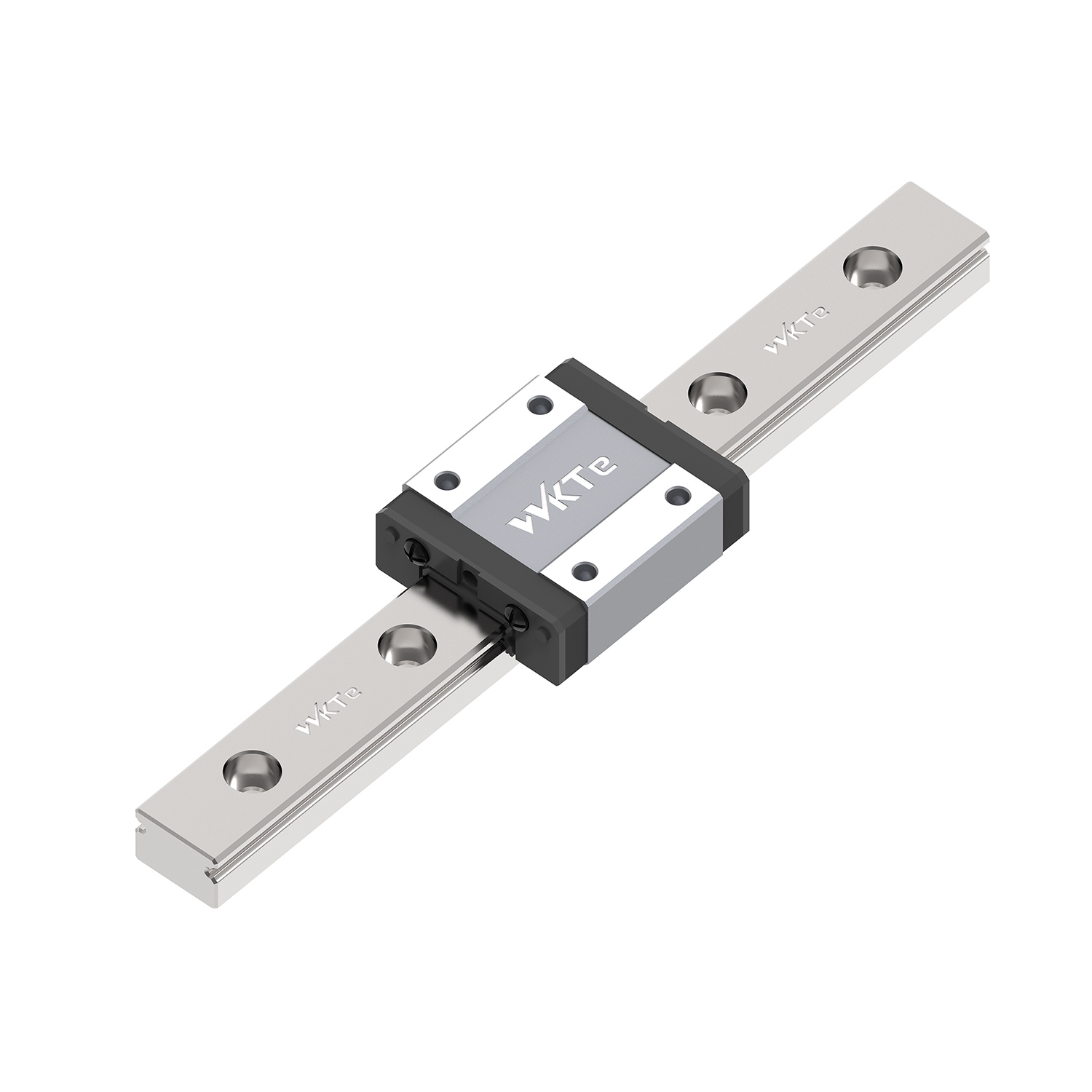
Profile rails feature flat, precision-ground raceways designed for four-point contact with the rolling elements. This architecture maximizes the contact area between the block and the rail. The design delivers exceptionally high load capacity in all radial, reverse-radial, and lateral directions. When you need to move heavy loads with high precision, profile rails are the default choice.
The primary advantage of a profile Linear guide rail is its compact footprint combined with massive rigidity. However, this rigidity comes with strict installation requirements. Profile rails are unforgiving to misalignment. They require highly machined mounting surfaces. Any variance in the machine bed will transfer directly to the bearing block, causing binding, increased friction, and rapid failure. You cannot bolt a profile rail to a piece of raw structural aluminum framing and expect smooth travel.
Round rail systems utilize linear ball bushings running on hardened steel shafts. The rolling elements make point contact with the convex surface of the shaft. This design inherently allows the bearing block to rotate slightly around the shaft axis, providing a degree of freedom that profile rails lack.
Round rails offer unique advantages for specific structural challenges. They can span gaps without continuous support underneath the shaft, making them ideal for gantry systems. Their self-aligning capabilities provide a high tolerance for poor mounting surfaces. They are generally more cost-effective and easier to install. The trade-off is significantly lower load capacity compared to profile rails. Unsupported shafts are also susceptible to deflection under heavy loads, which compromises positional accuracy in the center of the stroke.
The choice between rollers and balls dictates the system's stiffness and friction profile. Ball bearings create point contact with the raceway. They offer low friction, smooth travel, and excellent high-speed performance. Ball guides suit the vast majority of general automation tasks, from 3D printing to automated optical inspection.
Roller bearings create line contact with the raceway. This exponentially increases the contact area. Roller linear guides are mandatory for ultra-heavy machine tools, stamping presses, and injection molding machines. They provide maximum stiffness to resist heavy cutting forces. The line contact minimizes elastic deformation under load but restricts maximum travel speeds and requires significantly more force to overcome initial static friction.
Space-constrained applications demand specialized solutions. Miniature linear guides utilize a 2-row Gothic arch contact design to maintain load capacity within a tiny footprint. Rail widths can be as small as 3mm. These guides are essential for medical devices, pipetting robots, and compact optical inspection equipment. Despite their size, they require the same rigorous load and life calculations as standard guides. They are highly sensitive to contamination, requiring clean operating environments.
High-speed travel often generates unacceptable noise levels as rolling elements collide within the block. Manufacturers mitigate this by integrating ball chains or resin spacers between the rolling elements. This technology eliminates metal-to-metal contact inside the load zone.
The benefits extend beyond noise reduction. Caged designs improve grease retention by creating small lubrication pockets between the balls. This extends maintenance intervals significantly. The spacers also prevent the balls from skewing as they enter the load zone, resulting in smoother travel, lower heat generation at high speeds, and a more consistent friction profile across the entire stroke.
Guide Architecture | Primary Advantage | Primary Limitation | Ideal Application |
|---|---|---|---|
Profile Rail (Ball) | High rigidity, equal load capacity in all directions | Requires precision-machined mounting surfaces | General automation, packaging, assembly |
Profile Rail (Roller) | Maximum stiffness, extreme load capacity | Lower maximum speeds, higher friction | CNC machining, heavy presses |
Round Rail (Shafting) | Self-aligning, tolerates unmachined surfaces | Lower load capacity, shaft deflection | Gantry systems, material handling |
Miniature Guide | Ultra-compact footprint | Strict environmental sensitivity | Medical devices, optics, 3D printing |
Machine tools subject linear guides to extreme cutting forces and severe vibration. These applications demand high rigidity and heavy preload. Engineers typically specify roller-type profile rails to withstand these dynamic loads without deflecting. A deflection of even a few microns at the guide block translates to massive dimensional errors at the tool tip. Protection is equally critical. The guides must utilize metal scrapers and high-durability wipers to defend against hot metal swarf and aggressive cutting coolants that can destroy standard rubber seals in weeks.
Cleanroom environments prioritize contamination control over heavy load capacity. Motion systems here require low particulate generation to maintain Class 10 or Class 100 standards. Engineers select miniature or standard profile rails with low preload to minimize friction and wear. Standard steel rusts and standard grease outgasses in vacuums, contaminating silicon wafers. Modifications include stainless steel construction, vacuum-compatible low-outgassing grease, and specialized ball retainers to eliminate metal-to-metal friction and particle shedding.
Packaging equipment operates at high speeds with aggressive acceleration profiles over long travel lengths. Uptime is the primary metric. Ball-type profile rails or round rails are ideal for these dynamics. To minimize maintenance downtime, engineers integrate self-lubricating reservoirs or oil-impregnated pads directly into the bearing blocks. This ensures continuous lubrication without manual intervention, allowing the machines to run 24/7 across multiple shifts without stopping for grease application.
Laboratory automation requires smooth, whisper-quiet operation. Devices often operate in environments exposed to harsh cleaning chemicals and biological washdowns. Miniature stainless steel linear guide rails fit the compact size requirements of desktop analyzers. Specialized surface treatments, such as Raydent coating or hard chrome plating, provide the necessary corrosion resistance to survive frequent chemical exposure without degrading the raceway geometry.
Manufacturers categorize linear guides into standard accuracy classes: Normal, High, Precision, Super Precision, and Ultra Precision. These classes define the dimensional tolerances of the block and rail assembly. The most critical metric is travel parallelism. This measures the variance in height and width between the block and the rail over the entire stroke length. High-precision applications require minimal variance to ensure the tool tip or payload remains perfectly level during travel. For example, an Ultra Precision rail might guarantee a running parallelism of less than 3 microns over a 1-meter stroke, whereas a Normal class rail might allow 15 microns.
Standard linear guides use high-carbon bearing steel, typically 52100. This material offers optimal hardness for maximum load capacity and fatigue life. However, it rusts rapidly in damp environments. Martensitic stainless steel, like 440C, provides inherent corrosion resistance but sacrifices roughly 15% to 20% of the load capacity due to lower hardness. For extreme environments, engineers apply aftermarket surface treatments. Hard chrome plating, black chrome, and fluororesin coatings enhance environmental resistance without altering the base metal's structural properties. You must specify these treatments during the initial design phase, as they add microscopic thickness to the rail, requiring custom-matched bearing blocks.
The mounting orientation drastically shifts the load vectors applied to the bearing block. A horizontal mount places the load directly downward, which is the optimal scenario. Vertical, wall-mounted, or inverted orientations introduce complex forces. You must calculate Pitch, Yaw, and Roll moment loads. Pitch occurs during acceleration and deceleration. Yaw occurs from side loads or off-center drive mechanisms. Roll occurs when the center of gravity is offset from the rail center. Sizing the blocks requires compensating for these moment loads to prevent premature raceway spalling. Often, engineers use two blocks per rail and two parallel rails to convert moment loads back into standard radial loads.
Lubrication separates the rolling elements from the raceway. Without a microscopic film of oil or grease, the guide fails rapidly through cold welding and fretting. Grease is standard for most applications, offering good retention and simple maintenance. Lithium soap-based greases work well for general automation. Oil lubrication is necessary for ultra-high-speed operations to dissipate heat. To extend maintenance intervals, engineers integrate automated lubrication blocks. Oil-impregnated resin pads apply a continuous, micro-film of lubricant directly to the raceway, enabling near maintenance-free operation for thousands of kilometers.
A Linear guide rail must align perfectly with its chosen drive system. Whether using ball screws, rack and pinion systems, or linear motors, the guiding and driving elements must operate in parallel. You must match the accuracy class of the guide rail to the precision of the drive mechanism. Pairing an ultra-precision ground ball screw with a normal-class guide rail creates binding forces, uneven wear, and positional errors. The drive mechanism will attempt to force the payload in a perfectly straight line, while the guide rail will force it to follow its wider tolerance path. This fight destroys both components.
Inadequate parallelism between two parallel rails is the most common cause of system failure. Misalignment forces the bearing blocks to fight each other during travel. This causes severe binding, rapid raceway wear, and motor stalling. Mitigate this risk by specifying strict machining tolerances for the mounting shoulders. Utilize master/subordinate rail installation techniques. First, bolt the master rail against a precision-machined reference edge and torque it to spec. Next, mount the subordinate rail but leave the bolts slightly loose. Run the bearing blocks back and forth across the entire stroke. The subordinate rail will self-align to the master rail. Finally, torque the subordinate rail bolts down sequentially. If precision base machining is impossible, switch to round rails.
Dust, abrasive particulate, or coolant entering the bearing block will destroy the rolling elements. A single metal chip can fracture a ball bearing or score the raceway. Implement a layered defense strategy. Specify double lip seals to block fine dust. Use bottom seals to protect against upward splashes from cutting fluids. Install metal scrapers on the outside of the block to clear heavy debris and hot chips from the rail surface. Finally, use rail hole caps or continuous steel bellows to prevent contaminants from settling in the mounting bolt counterbores. Unplugged bolt holes act as collection pits for debris, which the block seals will eventually drag into the bearing.
In long-travel systems or high-heat environments, the machine bed and the steel rail expand at different rates. This differential thermal expansion causes the rail to warp, buckle, or shear its mounting bolts. Calculate the thermal expansion coefficients of all materials involved. An aluminum machine bed expands much faster than a steel guide rail. Mitigate warping by using floating bearing configurations on one side of a parallel system. For extremely long runs, use segmented rails with engineered expansion gaps at the joints, allowing the steel to grow without distorting the travel path.
Standard rail lengths typically max out around 4 meters due to manufacturing and shipping constraints. Long-travel gantries require joining multiple rails end-to-end. Improper joining causes block damage and rough transitions as the rolling elements cross the seam. Specify factory-ground butt joints for seamless transitions. Ensure strict alignment using precision straight-edges during installation. Always stagger the joints of parallel rails. If the left rail has a joint at 2 meters, place the right rail joint at 3 meters. This ensures the bearing blocks do not cross seams simultaneously, maintaining system rigidity and preventing sudden spikes in travel resistance.
Selecting the optimal linear guide rail is a rigorous exercise in balancing load capacity, environmental defense, material properties, and mounting surface realities. Defaulting to the highest accuracy class or the heaviest preload often introduces unnecessary friction and strict machining requirements that derail project timelines.
Follow a strict sequential decision framework. First, calculate all dynamic loads, static loads, and applied moments. Second, determine the required travel life based on duty cycles. Third, assess your machine base capabilities to choose between profile and round architectures. Fourth, select the appropriate preload and accuracy class. Finally, specify the seals and materials required to survive the operating environment.
Take the following actions to finalize your motion system design:
Download native 3D CAD models from the manufacturer to verify spatial constraints and mounting hole alignments against your machine bed.
Input your payload and acceleration data into online L10 life calculators to confirm your dynamic load ratings exceed the required travel life.
Review your environmental conditions and specify the exact seal codes required for protection against dust, fluids, or metal chips.
Consult an application engineer to verify moment load calculations for vertical or wall-mounted orientations before finalizing the bill of materials.
A: Profile rails feature flat raceways that offer high rigidity and massive load capacity in all directions, but they require precision-machined mounting surfaces. Round rails use ball bushings on cylindrical shafts, making them self-aligning and better suited for unmachined surfaces, though they have lower load capacities.
A: Lifespan is calculated using the L10 life equation. This formula factors in the basic dynamic load rating (C), the actual applied load, and several operational modifiers, including the hardness factor, temperature factor, contact factor, and load factor, to predict the travel distance before fatigue flaking occurs.
A: Preload is the practice of using oversized rolling elements to eliminate internal clearance between the block and the rail. This increases structural rigidity and positional accuracy, preventing deflection under heavy loads. However, it also increases internal friction and heat generation.
A: Yes, linear guides can be mounted vertically. However, vertical mounting shifts the load vectors, requiring careful calculation of pitch and yaw moment loads. Vertical systems also typically necessitate braking mechanisms or counterbalances to prevent the payload from back-driving and crashing during a power loss.
A: Prevent rust by specifying martensitic stainless steel components. For harsher chemicals, apply specialized anti-corrosion surface treatments like hard chrome plating or Raydent coatings. Additionally, use FDA-approved washdown greases and heavy-duty seals to protect the internal rolling elements from fluid ingress.
A: Binding usually occurs due to misalignment between parallel rails, causing the blocks to fight each other. It can also result from mounting the rails on an uneven surface, which twists the profile rail. Contamination inside the block or inadequate lubrication will also cause severe binding and rough travel.


