
Views: 0 Author: Site Editor Publish Time: 2026-07-23 Origin: Site


Achieving high precision in linear motion systems is rarely as simple as purchasing a premium, high-grade component. You might expect an expensive mechanical part to guarantee flawless movement automatically within your machine assembly. However, the core engineering reality reveals a much more complex interaction between mechanics, environment, and installation quality. Over-specifying precision grades often wastes your valuable project budget without delivering any tangible performance benefits on the floor. Conversely, under-specifying these vital components leads directly to system deflection, premature mechanical wear, and rejected manufactured parts. Striking the right engineering balance matters deeply for operational success and long-term efficiency. This article deconstructs the exact variables dictating real-world accuracy across various industrial setups. We aim to bridge the critical gap between theoretical catalog specifications and actual on-site performance. By the end, you will understand how to evaluate, shortlist, and source optimal components for your specific requirements.
Component-level precision (grades N through UP) establishes a baseline, but system accuracy is heavily dictated by mounting surface tolerances.
Applying the correct preload eliminates radial clearance and increases rigidity, directly impacting dynamic accuracy under load.
Thermal expansion and environmental contamination are the most common uncalculated risks that degrade precision over time.
Specifying linear guide rails requires a cost-benefit analysis between absolute micron-level accuracy and commercial viability.
Industry standard lenses categorize manufacturing tolerances to help engineers make informed decisions. Manufacturers classify Linear Guide Rails using highly specific accuracy grades. The most common tiers include Normal (N), High (H), Precision (P), Super Precision (SP), and Ultra Precision (UP). These labels define the maximum allowable microscopic deviations introduced during the complex factory grinding process. Higher grades undergo extended grinding cycles in temperature-controlled environments to minimize geometric errors.
Engineers focus primarily on two critical evaluation dimensions when assessing baseline mechanical accuracy. The first is dimensional tolerance. This metric defines the permissible variance in overall height and width between multiple blocks mounted on the same rail. If you place two carriage blocks side-by-side, they must share nearly identical dimensions to distribute heavy loads evenly. The second crucial metric is running parallelism. This specific measurement tracks the maximum deviation in vertical and horizontal alignment as the carriage block travels the full length of the track.
Accuracy Grade | Typical Height Variance (Microns) | Running Parallelism (Per 1000mm) | Primary Application Focus |
|---|---|---|---|
Normal (N) | ± 100 | ~ 15 microns | Conveyors, Basic Automation |
High (H) | ± 40 | ~ 7 microns | CNC Routers, Packaging |
Precision (P) | ± 20 | ~ 3 microns | Laser Cutting, Printing |
Super Precision (SP) | ± 10 | ~ 2 microns | Medical Imaging, Grinders |
Ultra Precision (UP) | ± 5 | ~ 1 micron | Semiconductor, Metrology |
You must place these specifications into proper decision-stage context during the design phase. You need to match the selected precision grade directly to your application's fundamental success criteria. Packaging machinery and basic material handling systems operate perfectly well using Normal or High grades. In stark contrast, semiconductor wafer inspection equipment absolutely requires Super Precision or Ultra Precision hardware. Upgrading a standard packaging machine to a UP grade offers zero practical benefit while massively inflating procurement costs.
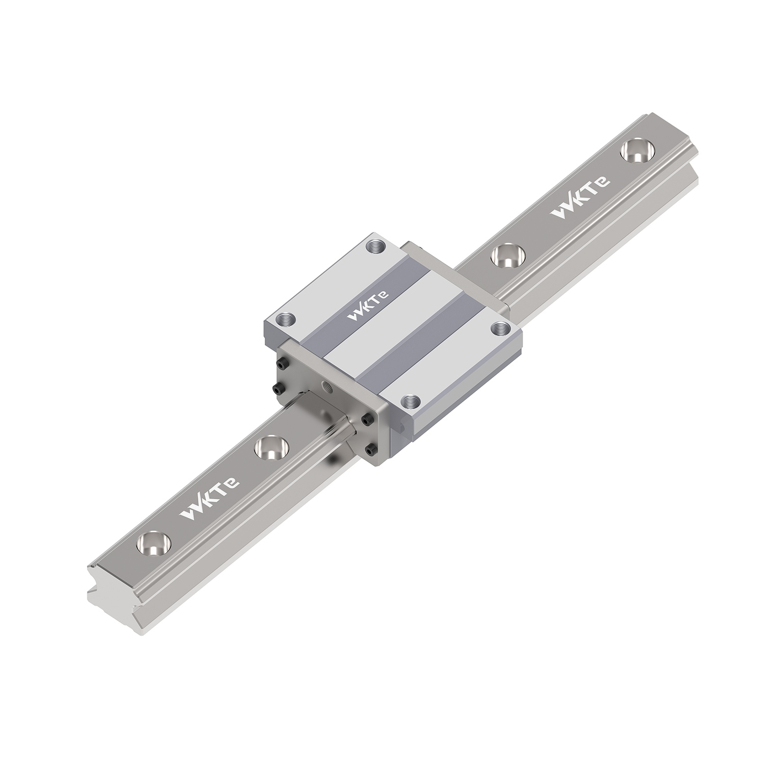
The "weakest link" principle completely dominates complex mechanical assemblies. You can purchase the highest-grade hardware available on the industrial market today. However, these stiff steel tracks will inevitably deform to mirror an improperly machined mounting bed. Bolt tension forces the rail to conform precisely to the base profile beneath it. This unavoidable physical reality completely negates your heavy financial investment in premium precision hardware.
You must pay close attention to several critical installation factors to preserve system accuracy:
Base Machining Requirements: Your mounting surface must exhibit exceptional flatness and straightness. A warped cast iron bed guarantees a warped travel path. Many builders use precision hand-scraping techniques on the bed to ensure a perfectly planar mounting surface.
Lateral Push Forces: Alignment requires much more than just tightening vertical mounting bolts. You must utilize precisely machined reference edges and datum planes. We strongly recommend using lateral mounting bolts to secure alignment against the reference edge permanently.
Parallelism Between Rails: Dual-rail setups introduce complex binding risks. If two parallel tracks diverge even slightly, the system experiences severe friction spikes. This misalignment forces the drive motor to work significantly harder, generating excess heat and accelerating component wear.
Let us perform a trustworthiness and assumption check regarding system design. Many engineers mistakenly assume higher-grade components inherently fix underlying accuracy issues. In reality, allocating budget toward a stiffer, flatter machine base consistently yields better engineering returns. A standard grade rail mounted on a perfectly flat bed consistently outperforms an ultra-precision rail bolted to an uneven, poorly machined surface.
A perfectly aligned rail will still lose accuracy dynamically during actual operation. This phenomenon happens if the block deflects under external operational forces. As the machine accelerates or cuts hard material, it subjects the carriage to extreme pitch, yaw, and roll forces. Even minor microscopic gaps between the rolling elements and the steel raceway allow unwanted angular shifting.
How do we solve this dynamic deflection problem? Manufacturers apply internal preload to eliminate this radial clearance. They insert intentionally oversized rolling elements—such as steel balls or cylindrical rollers—into the carriage block. This creates a permanent state of negative clearance. The internal components remain constantly compressed against the raceway walls. This physical compression drastically increases overall mechanical rigidity and directly improves dynamic accuracy.
You must evaluate several crucial trade-offs when selecting specific preload levels:
Light vs. Heavy Preload: You must balance the absolute need for high rigidity against inherent physical penalties. Heavy preload significantly increases internal running friction.
Heat Generation: Increased friction inherently generates much more thermal energy during continuous high-speed travel.
Operational Lifespan: Constant heavy compression naturally accelerates the rolling contact fatigue life of the balls and raceways.
Dynamic Accuracy Preservation: Preload effectively prevents the block from vibrating or shifting. This holds true even when subjected to aggressive external cutting forces or rapid acceleration profiles.
Static, room-temperature specifications rarely match your actual factory floor realities. Real-world operating conditions introduce dynamic environmental variables affecting physical dimensions over time. High-speed operation, heavy payloads, and aggressive duty cycles generate substantial kinetic energy.
Consider these primary environmental degradation factors. First, thermal expansion changes everything within a precise mechanical system. When ambient heat rises or components generate internal friction, the steel expands. This microscopic expansion alters internal clearances and shifts the theoretical axis of motion. A system perfectly aligned at 20 degrees Celsius may bind or drift significantly at 45 degrees Celsius.
Second, lubrication film thickness plays a surprisingly hidden role in vertical accuracy. Oil or grease creates a microscopic fluid boundary layer between the steel balls and the raceway. Improper or degraded lubrication introduces micro-variations in running height. Too much thick grease can actually lift the block slightly during travel, while too little causes destructive metal-to-metal contact.
Finally, environmental contamination destroys precision rapidly. Airborne dust, metal swarf, and coolant debris eventually compromise the exposed rolling element tracks. This intrusion leads to an immediate loss of smooth accuracy and eventual catastrophic system failure.
You need a robust mitigation strategy to combat these operational issues. Shortlist the correct sealing solutions early in the engineering design phase. Specify double end seals, robust metal scrapers, and protective bellows for harsh manufacturing environments. Additionally, automated centralized lubrication systems help maintain consistent fluid film thickness. This proactive approach ensures long-term operational accuracy for your Linear Guide Rails.
Engineering procurement requires a strict business outcome focus. You need a highly reliable framework for evaluating the cost implications of increasing accuracy requirements. Demanding tighter tolerances universally drives up manufacturing expenses and lengthens project timelines.
Examine the primary cost drivers in this specialized industry. Premium steel materials, exhaustive factory grinding processes, and tighter quality control significantly increase the final unit cost. Furthermore, ultra-precision components often require extended production lead times because they demand specialized manufacturing environments and rigorous laser testing.
You should also proactively evaluate software-based accuracy alternatives. Sometimes, relying purely on mechanical component accuracy proves financially inefficient. Instead, modern engineers often pair a standard track with high-resolution optical linear encoders. The control system uses this precise closed-loop feedback for constant software compensation. The machine controller adjusts the drive motor dynamically to correct physical mechanical deviations in real-time.
Before finalizing the Bill of Materials (BOM), take specific analytical next steps. Consolidate your exact payload data, operational stroke length, and strictly required repeatability metrics. Consult directly with application engineers to verify your mathematical assumptions. This collaborative technical approach prevents costly over-specification and ensures the selected hardware matches your precise performance targets perfectly.
Linear guide rail accuracy remains a complex, system-wide engineering challenge rather than an isolated product specification. Success depends entirely on integrating multiple mechanical disciplines effectively. We can summarize this engineering challenge into a critical triad: baseline component grade, mounting surface integrity, and appropriate internal block preload. Ignoring any single element compromises the entire motion assembly.
Review your current system designs to identify potential weak points in machine bases or operational lubrication strategies. Prioritize bed flatness before spending budget on ultra-precision hardware. Contact technical sales teams today to request a comprehensive application review. You can also download a 3D CAD model and utilize an online sizing calculator to begin your optimal specification process immediately.
A: Accuracy refers to hitting an exact, absolute target position within a specified coordinate system. It measures how close the carriage gets to the commanded destination. Repeatability measures the system's ability to return to that exact same position consistently over multiple operating cycles. A motion system can be highly repeatable but functionally inaccurate if it constantly returns to the exact wrong location.
A: Running parallelism deviation naturally compounds over longer physical strokes. Factory grinding processes struggle to maintain perfect straightness over several meters of solid steel. Furthermore, long travel lengths often require jointed or butt-spliced rails. These physical joints introduce specific alignment challenges. Improperly mated joints cause micro-shocks, which momentarily degrade running accuracy and accelerate wear at the seam.
A: You generally cannot achieve higher precision by simply swapping carriage blocks. Component interchangeability realities dictate that unmatched block and rail sets default to the lower accuracy tier. High-precision components are factory-matched and ground together as a unique pair. Mixing grades often causes uneven preload, unexpected friction spikes, and accelerated track wear. Always replace them together.


