
Views: 0 Author: Site Editor Publish Time: 2026-07-23 Origin: Site


Selecting linear motion systems requires looking far beyond top-line load ratings. The internal architecture strictly dictates long-term reliability and machine performance. Engineers must understand how these complex mechanisms truly operate beneath the surface. Premature system failure, excessive maintenance downtime, and frustrating precision loss often stem from one critical misstep. Technical teams frequently specify the wrong internal components for a uniquely harsh operating environment. Standard, off-the-shelf configurations simply cannot survive heavy vibration or extreme particulate contamination.
We will break down the exact anatomy of Linear Guide Rails step by step. This deep dive helps technical buyers and engineering teams evaluate specific design features against tangible operational outcomes. You will discover exactly how every internal part influences overall motion control success. By understanding these structural nuances, you can confidently match system capabilities to real-world industrial demands.
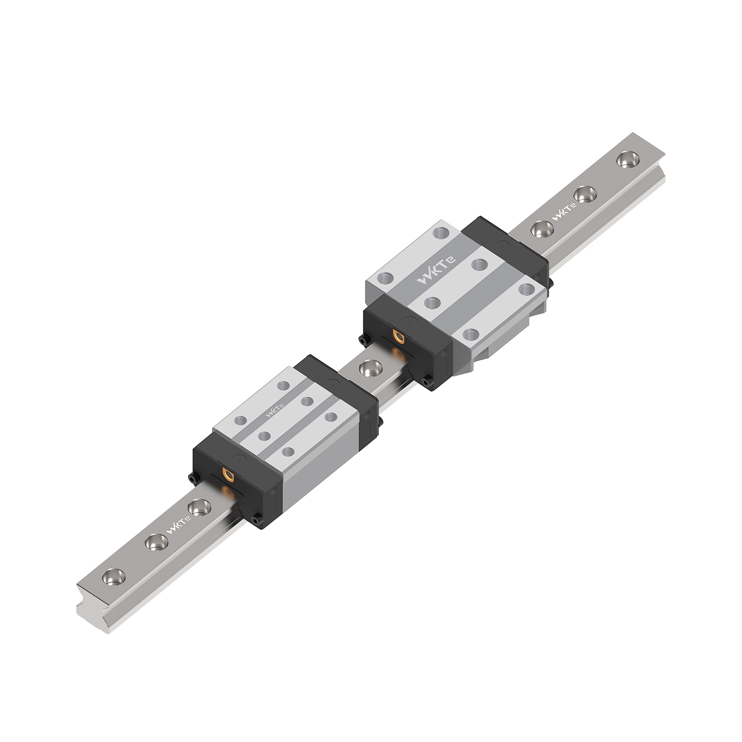
A standard linear guide system consists of four primary structural components: the profiled rail, the carriage (block), the rolling elements, and the recirculation system.
Secondary components like seals, scrapers, and ball retainers dictate environmental resilience and maintenance frequency.
Selecting between ball and roller elements is the most critical decision, balancing dynamic load capacity against friction and speed capabilities.
Proper component specification requires calculating real-world factors like structural misalignment, shock loads, and chemical exposure, not just theoretical lifespan.
Every linear motion system relies on a unified mechanical structure. You will find four primary structural components doing the heavy lifting. Each part must function perfectly to ensure smooth, repeatable travel across the entire stroke length.
The profiled rail acts as the foundational track for the entire assembly. Manufacturers precision-grind its external raceways. These specialized grooves actively guide the rolling elements. Evaluation points matter greatly during the specification phase. You must choose between top-down and bottom-up mounting hole configurations. Top-down mounting simplifies the initial installation process. Bottom-up mounting keeps the top surface completely smooth. This prevents hazardous debris accumulation inside the bolt holes. Material composition also plays a massive role. Standard carbon steel works perfectly for general factory automation. However, you should specify corrosion-resistant alloys for chemically aggressive environments.
The carriage serves as the main load-bearing unit. Engineers frequently call it the runner block. It supports the external payload while traveling along the rail. You must evaluate different structural form factors. Flanged blocks offer significantly broader mounting surfaces. They handle heavy, wide machine loads effectively. Narrow or unflanged blocks save critical space. They fit perfectly inside highly compact machine assemblies. Your choice directly impacts the overall footprint of the motion stage.
Rolling elements sit securely between the carriage block and the track. They facilitate low-friction motion under immense pressure. You must choose either spherical balls or cylindrical rollers. Ball bearings handle high-speed operations beautifully. They offer excellent multi-directional load distribution. They even provide slight self-aligning capabilities to forgive minor structural inaccuracies. Cylindrical rollers function differently. They deliver ultra-high rigidity for heavy industrial tasks. They achieve massive heavy-duty load capacities through line contact. Balls only offer point contact. Line contact spreads the applied force over a much wider physical area.
Below is a comparative chart detailing the operational differences between these elements.
Performance Criteria | Ball Bearings | Cylindrical Rollers |
|---|---|---|
Load Capacity | Moderate to High | Ultra-High |
Friction Level | Very Low | Moderate |
Contact Profile | Point Contact | Line Contact |
Best Application | High-speed automation | Heavy CNC machining |
The recirculation system enables continuous, infinite linear motion. Rolling elements need a physical return path once they exit the load zone. Polymer end caps actively guide them out of this high-pressure area. Return tubes then route them safely back to the starting position. This continuous internal loop prevents the system from seizing. A robust recirculation system ensures seamless travel regardless of the rail length.
Basic structural parts merely enable motion. Secondary components actually keep the system alive in harsh settings. They dictate environmental resilience and dictate your overall maintenance frequency.
Seals and scrapers provide vital environmental protection. End seals block micro-contaminants at the front and rear carriage edges. Side seals actively prevent internal lubricant leakage along the lower profile. Metal scrapers handle highly aggressive physical threats. You absolutely need them when facing hot chips or weld spatter. Heavy, sharp debris will destroy standard rubber seals instantly. Neglecting these secondary protective parts guarantees premature bearing failure.
Cages and retainers manage internal friction masterfully. They utilize advanced polymer strips to separate individual rolling elements. This deliberate separation eliminates harmful metal-to-metal contact inside the block. Balls no longer grind against each other during high-speed travel. This specific mechanism significantly reduces operational noise. It also sharply lowers internal heat generation. Consequently, you extend the system maintenance intervals significantly. Factories experience fewer unexpected shutdowns as a direct result.
Proper lubrication keeps the mechanical system running smoothly. Standard grease nipples allow routine manual or automated lubrication. You can connect them directly to centralized factory pumps. Integrated lubrication units take this concept further. They utilize internal oil-impregnated pads. These specialized pads wipe the track continuously during operation. They offer maintenance-free operation for thousands of kilometers. This feature drastically reduces daily servicing tasks for maintenance teams.
You cannot buy linear motion components blindly. You must evaluate various configurations against your specific application needs. A mismatch here leads to immediate operational degradation.
Manufacturers create internal preload by inserting slightly oversized rolling elements. We call this internal tension preload. It balances system rigidity against rolling friction. Heavy preload serves large machine tools perfectly. Heavy-duty milling machines require absolute rigidity. They cannot tolerate any clearance or structural play. Light or zero preload fits entirely different applications. It guarantees highly smooth motion. It requires minimal driving motor force. You typically use zero preload in quiet, non-vibrating cleanroom environments.
Material and coating specifications solve unique environmental challenges. Standard steel rusts quickly in damp facilities. Specialized surface treatments like Raydent or hard chrome prevent severe surface oxidation. Black chrome plating ensures strict semiconductor vacuum compliance. Stainless steel components serve highly specific regulatory needs. Medical devices require stringent hygiene standards. Food-grade washdown applications mandate high-grade stainless steel. Ordinary steel fails rapidly under high-pressure chemical washdowns.
Accuracy grades define your precision-to-cost ratio. Accuracy directly measures the running parallelism between the mounted rail and moving carriage. Available grades range from Normal up to Ultra-Precision. You must align these designated classes with actual machine requirements. Over-engineering wastes budget unnecessarily. A standard cardboard packaging machine rarely needs ultra-precision grades. Conversely, a highly precise optical inspection system absolutely requires them. Match the specified grade strictly to your actual engineering tolerance limits.
Even premium components fail if implemented poorly. Understanding these risks helps you design a much more resilient machine architecture.
Installation Misalignment: This remains the primary culprit for premature system death. Mechanics sometimes mount parallel rails unevenly. This creates severe binding forces across the carriage block. The carriage raceways suffer extreme premature wear. The rolling elements experience rapid, catastrophic metal fatigue.
Lubrication Starvation: Running a system dry ruins it quickly. It immediately causes localized surface flaking. Metal fatigue accelerates rapidly without a protective oil film. You must ensure highly accessible lubrication ports. Automated delivery systems prevent costly human error. They deliver exact lubricant volumes consistently.
Contaminant Ingress: Foreign particles destroy delicate internal mechanics. Inadequate sealing allows abrasive particulate matter inside the block. Dust and metal chips bypass the damaged end caps. They enter the sensitive recirculation mechanism. This foreign material jams the return tubes permanently. The motion becomes rough, loud, and grinding.
System-Level Integration Risks: Engineers occasionally fail to account for machine base deflection. A weak structural frame bends noticeably under dynamic operation. This bending shifts heavy loads unpredictably onto the Linear Guide Rails. The internal components endure concentrated stresses far beyond their rated capacity.
Specifying complex mechanical systems requires a structured, logical approach. You must move step by step to avoid costly oversights during procurement.
Define System Requirements First: Establish your core numerical requirements. Calculate the equivalent dynamic load accurately. Determine your required travel life in kilometers. Pinpoint the maximum operating speed. These specific numbers form your baseline engineering criteria.
Environmental Assessment: Conduct a thorough environmental audit. Map out all factory temperature extremes. Identify any potential chemical exposure. Categorize the specific airborne particulate types. A pharmaceutical cleanroom demands completely different seals than a dusty sawmill. These external factors strictly dictate your internal sealing and material choices.
Interchangeability Considerations: Consider part interchangeability requirements early. Some global manufacturers offer fully interchangeable blocks and rails. You can swap them independently on the factory floor. This aids localized maintenance efforts immensely. It also dramatically reduces your spare parts inventory. Other brands require strictly matched sets. You must replace the entire integrated assembly if one single part fails.
Next Step Actions: Take explicit engineering next steps. Request detailed 3D CAD models for your digital assembly tests. Consult directly with specialized applications engineers. They help optimize your final preload and accuracy pairings. Review prototype lead times carefully. Supply chain delays can derail your entire project schedule if ignored.
A linear guide rail is never just a simple industrial commodity. It functions as a deeply integrated system of highly specialized components. Every internal part—from the polymer return tubes to the metal side seals—plays a crucial role in overall performance. We strongly recommend basing your final procurement decisions on an exact architectural match. Align your specific seal types, roller designs, and steel materials with reality. They must survive the harsh physical realities of your intended operating environment. Ignore theoretical performance on paper. Focus entirely on how these physical components endure daily industrial abuse. Proper upfront specification guarantees years of smooth, uninterrupted machine operation.
A: No. While dimensions may look identical, internal raceway profiles, ball sizes, and contact angles vary significantly between brands. Mixing components from different manufacturers causes immediate binding, unpredictable friction, and rapid mechanical failure. Always specify components from the same manufacturer unless using universally standardized, interchangeable sub-components from a single brand.
A: Point contact occurs in ball-type guides where spherical balls touch the raceway at concentrated, tiny points. This reduces friction for high speeds. Line contact occurs in roller-type guides where cylindrical rollers touch the raceway along a continuous line. This provides massive structural rigidity and superior heavy-load capacity.
A: Ball cages trap specific amounts of grease around each rolling element. They eliminate metal-to-metal friction between the balls, drastically reducing internal heat generation. This efficient lubricant retention can extend maintenance intervals by thousands of kilometers, often enabling near maintenance-free operation in clean environments.
A: Specify top-mounting rails for easier installation and accessibility, as you drive bolts downward into the machine base. Specify bottom-mounting rails (tapped from below) when you need a perfectly smooth upper rail surface. Bottom-mounting prevents dust, fluids, or metal chips from collecting inside the bolt holes.
A: The dynamic load rating is determined by calculating the constant load under which a specific percentage (usually 90%) of a group of identical linear guides can travel a defined distance (typically 50km or 100km) without showing signs of material flaking or fatigue on the raceways or rolling elements.


