
Views: 0 Author: Site Editor Publish Time: 2026-07-08 Origin: Site


Specifying Linear Guide Rails is rarely a straightforward hardware swap. An undersized rail often leads to catastrophic failure. Conversely, an oversized component quickly inflates system mass and physical footprint. This dynamic makes component selection absolutely critical for long-term machine reliability. For mechanical engineers, system integrators, and procurement teams, evaluating linear motion systems means finding a delicate balance. You must carefully weigh dynamic load ratings against accuracy classes and strict environmental constraints. A minor miscalculation can severely compromise precision and drastically reduce operational lifespan.
We have developed this transparent, evidence-based framework to simplify your complex design process. You will learn how to accurately specify these components to maximize theoretical lifespan (L10). Furthermore, this guide explores architecture choices, step-by-step evaluation methods, and critical implementation realities you must consider before finalizing your design.
Selection must begin with application orientation (horizontal, vertical, wall-mounted) to accurately calculate equivalent dynamic loads.
Preload levels dictate the trade-off between system rigidity and frictional resistance; over-preloading is a primary cause of premature wear.
Standardizing on ISO/DIN rail dimensions ensures vendor interchangeability and mitigates supply chain risks.
Environmental factors—specifically the selection of seals, scrapers, and lubrication methods—frequently override baseline load calculations in determining actual rail lifespan.
Unplanned downtime in automated systems frequently traces back to misaligned or improperly specified linear guides. Success relies entirely on matching the guide's inherent capabilities to the machine's exact motion profile. Engineers often make the mistake of over-specifying load capacity without considering the geometric limitations of the operating environment. You must define clear, mathematical success criteria before looking at manufacturer catalogs.
Evaluating space constraints against required load capacity forms the foundation of your design. Smaller carriages require higher-density load ratings to function effectively. For example, when you lack the physical space for a large bearing block, you might need to switch from a ball-type system to a roller-type system. Rollers provide a larger contact area within the same dimensional envelope. This allows you to handle massive forces without increasing the machine's overall footprint.
Establishing acceptable nominal life is equally important. Engineers refer to this as the L10 life. You calculate L10 based on cycle times, travel speeds, and specific acceleration profiles. Rapid acceleration generates significant peak loads. These peak loads degrade the rolling elements much faster than steady-state cruising speeds. Therefore, you must capture the entire duty cycle. You need to know exactly how often the machine stops, starts, and changes direction to ensure the system survives its intended lifespan.
Manufacturers design different architectures to solve specific engineering challenges. Understanding the fundamental differences between these categories ensures you select the correct technology for your specific application.
Profiled ball designs represent the industry standard for most general applications. They utilize spherical rolling elements running through precise raceways. You will typically find them in general factory automation, CNC machinery, and packaging lines. They deliver an excellent balance of high travel speed, low internal friction, and multi-directional load capacity. Because they use point contact, they run smoothly and generate minimal heat.
Heavy-duty machine tools and industrial stamping presses demand extreme rigidity. Roller guides replace spherical balls with cylindrical rollers. This creates line contact rather than point contact between the rolling element and the raceway. This design delivers extreme structural rigidity and ultra-high load capacities. However, it comes at the expense of higher friction. You must account for increased motor torque requirements when specifying roller systems.
Some applications require microscopic precision within tiny physical envelopes. Semiconductor manufacturing, medical device assembly, and industrial 3D printing frequently utilize miniature guides. These systems feature a highly compact footprint. Manufacturers typically construct them from specialized stainless steel to ensure corrosion resistance. This makes them highly suitable for strict cleanroom environments where rust and particulate shedding are unacceptable.
Modern linear guides often feature caged ball technology. Traditional full-complement designs pack as many balls into the raceway as possible. This maximizes load capacity in a given physical space. However, the balls rub against each other, generating friction and noise. Caged designs place a synthetic retainer between each ball. This eliminates ball-to-ball friction entirely. It significantly reduces operational noise, lowers heat generation, and retains grease better, thereby extending maintenance intervals.
Architecture Type | Contact Method | Primary Advantage | Ideal Application |
|---|---|---|---|
Profiled Ball | Point Contact | Balanced speed and friction | Packaging, Automation |
Roller | Line Contact | Extreme load rigidity | Stamping, Heavy CNC |
Miniature | Point Contact | Compact, corrosion-resistant | Semiconductor, Medical |
Caged Ball | Isolated Point Contact | Low noise, extended lubrication | High-speed, Quiet zones |
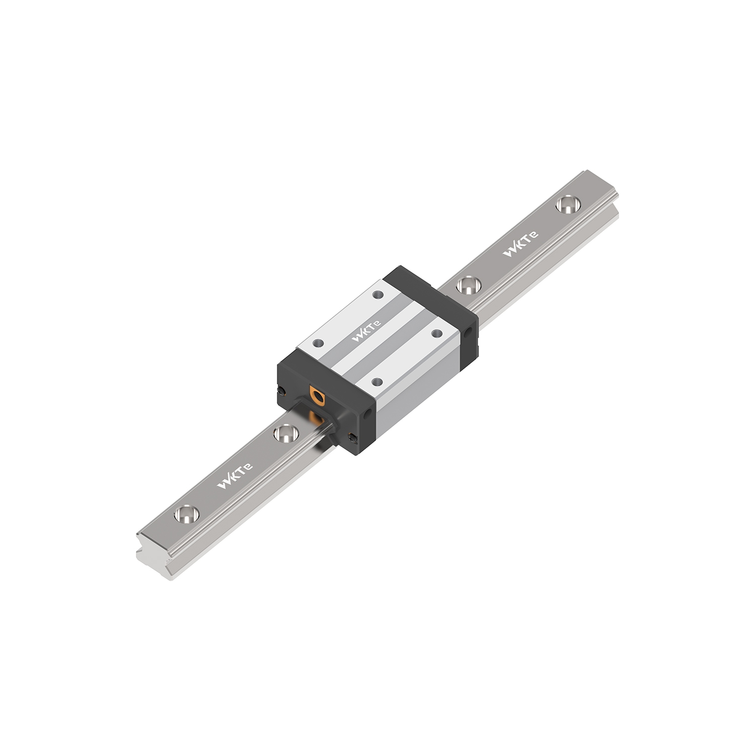
Following a strict mathematical approach eliminates guesswork. This five-step framework helps you map environmental variables directly to manufacturer specifications.
Calculating Applied Loads (Static & Dynamic): You must map every directional force acting on the carriage. This includes radial loads (pushing down), reverse-radial loads (pulling up), and lateral loads (pushing sideways). Additionally, you must apply appropriate safety factors based on vibration and impact conditions. A machine experiencing heavy shock loads requires a much higher static safety factor than a smooth-running inspection camera.
Sizing the Rail Width and Block Type: Once you determine the load, you evaluate physical sizing. You must compare standard rails against wide rails. Wide rails handle moment loads (twisting forces) much better, sometimes allowing you to use a single rail instead of a parallel pair. Next, select your block type. Flanged blocks allow both top and bottom mounting, giving assembly technicians flexibility. Narrow or square blocks typically only allow top mounting but save crucial horizontal space.
Specifying Accuracy Classes: Accuracy classes range from Normal (C) to High (H), Precision (P), Super Precision (SP), and Ultra Precision (UP). Higher accuracy minimizes running parallelism errors, ensuring the carriage moves in a perfectly straight line. However, specifying a higher accuracy class demands much tighter machining tolerances on your mounting base. Placing an Ultra Precision block on an uneven aluminum extrusion guarantees failure.
Determining Preload (Clearance vs. Rigidity): Preload removes internal clearance by using slightly oversized rolling elements. Normal clearance (Z0) allows for very smooth movement and forgives slight mounting errors. Light preload (Z1) provides general rigidity for standard automation. Heavy preload (Z2) serves machining applications requiring absolutely zero backlash. When selecting Linear Guide Rails, remember this risk: unnecessary preload rapidly accelerates fatigue life and increases required motor torque.
Verifying L10 Nominal Life: Finally, you execute standard life calculations. You use the basic dynamic load rating (C), the calculated applied load, and specific speed factors. This mathematical proof ensures your chosen components will meet the operational guarantees you promised your client.
Theoretical calculations mean nothing if you ignore real-world implementation. A perfectly specified guide will destroy itself in weeks if installed incorrectly or protected poorly.
Mounting surface preparation dictates the ultimate success of the system. Linear guide rails inherently conform to the surfaces beneath them. If you bolt a highly accurate rail to a warped steel frame, the rail will bend to match that warp. This forces the bearings to bind as they travel. You must provide precision-ground mounting bases to prevent this binding. The machining tolerance of your base must match or exceed the accuracy class of the rail.
Misalignment tolerances represent another critical risk. Engineers often design systems utilizing two parallel rails to support wide loads. If these two rails are not perfectly parallel in both horizontal and vertical planes, the carriages will fight each other. This creates massive internal stress. You must analyze the risks of using multiple rails and design proper compliance into your system to absorb minor variations.
Contamination destroys more bearings than heavy loads. You must tailor your sealing strategy to your environment. Standard end seals work fine for clean factories. However, harsh environments demand upgrades. Woodworking or metal grinding applications require aggressive metal scrapers to push heavy chips away. Alternatively, cleanrooms require specialized low-particulate seals to prevent grease from escaping into the environment.
Best Practice: Always use double seals and metal scrapers in environments containing fine ceramic dust, glass shards, or coolant spray.
Common Mistake: Relying on standard factory seals in heavy welding environments, leading to rapid raceway scoring from weld spatter.
Lubrication protocols dictate long-term survival. You must choose between grease and oil based on travel speed and orientation. Grease stays in place better for vertical applications, while oil provides excellent cooling for ultra-high-speed horizontal movements. Inadequate lubrication intervals cause rapid metal-to-metal wear. If your maintenance team historically ignores scheduled greasing, you should invest in long-term maintenance-free cartridges. These self-lubricating blocks slowly release oil into the raceways over years of operation.
Transitioning from engineering design to procurement requires strategic thinking. Your component choice impacts future supply chain stability and system maintainability.
Procurement teams should strongly favor standardized dimensions. Many global manufacturers follow specific ISO and DIN dimensional standards for overall height, width, and mounting hole spacing. Standardizing on these dimensions helps you avoid permanent vendor lock-in. If your primary supplier experiences a sudden factory shutdown, standard dimensions allow you to source a drop-in replacement from a competitor without redesigning your entire machine.
You must balance specialized features against off-the-shelf availability. Custom lengths, specialized platings, or custom joint-rails drastically increase lead times. For instance, requesting Raydent plating or hard chrome for extreme rust prevention might add months to your delivery schedule. You should evaluate whether you truly need custom features or if standard protective bellows could solve the environmental problem using stock parts.
Take these actionable next steps to finalize your specification. First, consolidate your load profile data, ensuring you capture maximum peak forces. Second, download the relevant 3D CAD models from the manufacturer and drop them into your assembly to verify spatial clearances. Finally, consult directly with the manufacturer's application engineers. Having an expert verify your theoretical life calculations before you issue a final purchase order is the best way to mitigate risk.
Selecting Linear Guide Rails is an exercise in managing complex engineering trade-offs. You must constantly balance system rigidity against rolling friction, and high load capacity against spatial constraints. Every decision, from choosing between ball and roller architectures to specifying exact preload levels, directly impacts how your machine will perform in the field.
By rigorously following a mathematical selection framework and accounting for harsh environmental realities, engineers can successfully prevent premature failure. Proper attention to mounting precision, aggressive sealing, and consistent lubrication will drastically optimize overall machine performance. We recommend utilizing manufacturer sizing calculators, downloading verified 3D CAD libraries, and contacting technical sales teams for a comprehensive application review before finalizing your designs.
A: C0 determines the maximum load a guide can handle before permanent plastic deformation occurs in the raceway or rolling elements. It applies when the guide is stationary or moving extremely slowly. Conversely, C is the dynamic rating used to calculate the theoretical fatigue life (L10) during continuous motion and varying speeds.
A: Preload eliminates internal backlash and significantly increases system rigidity by applying constant internal stress to the rolling elements. However, this continuous internal stress reduces the overall theoretical fatigue lifespan and increases friction. You must balance the need for precision against the reduction in nominal life.
A: While many manufacturers follow ISO/DIN dimensional standards for overall height and mounting hole spacing, internal ball raceway designs vary significantly. Mixing brands between a block and a rail is strongly discouraged due to precision mismatch and voided warranties. Complete rail-and-block assemblies, however, are often interchangeable.
A: The most common causes are lubrication starvation, contamination ingress from improper sealing, and geometric misalignment. If mounting surfaces are not precision-ground, the rails twist. This misalignment forces the bearings to bind, rapidly generating heat, destroying the rolling elements, and causing premature catastrophic failure.


