
Views: 0 Author: Site Editor Publish Time: 2026-09-12 Origin: Site


In industrial automation and machine design, the reliability of a linear motion system dictates the overall precision, acoustic profile, and lifespan of the equipment. Specifying the wrong linear motion component leads to two costly outcomes. You either over-engineer the system, adding unnecessary rigidity and complexity, or you under-engineer it, risking premature wear, deflection, and catastrophic system failure. Navigating the overlap in terminology between a profile rail and standard linear bearings requires a strict evaluation of load capacities, moment resistance, and mounting tolerances. Engineers must look beyond basic load ratings. You have to consider the physical mounting environment, the presence of contaminants, and the required maintenance intervals. Making the right choice ensures your machinery operates smoothly without unexpected downtime. We will break down the exact technical differences to help you specify the correct components for your next build.
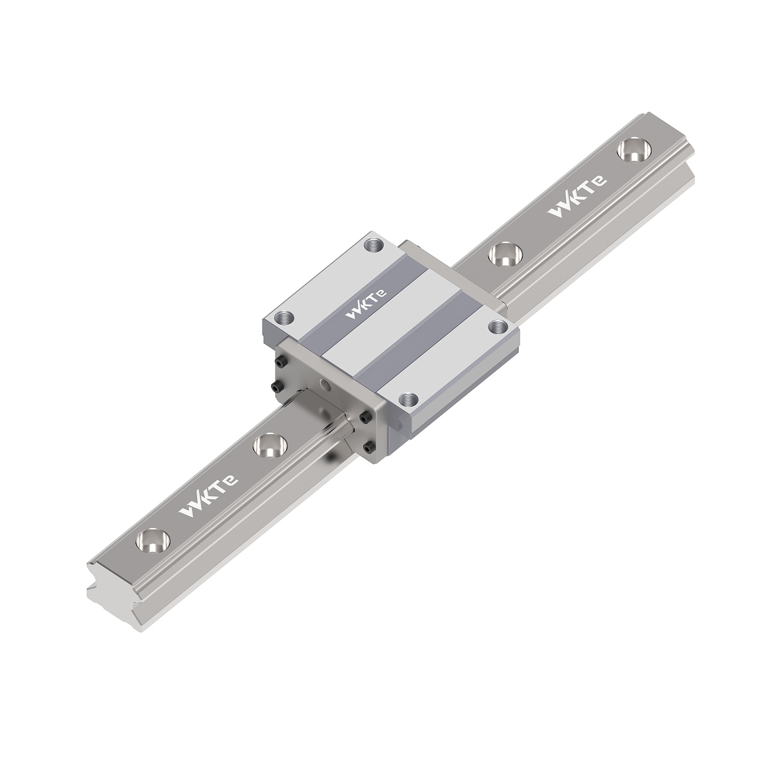
A Linear guide rail consists of a square or rectangular steel rail featuring precision-ground raceways. This rail pairs with a carriage, often called a block, which contains recirculating balls or cylindrical rollers. Engineers specify these components when applications demand absolute rigidity and high-precision positioning. The manufacturing process involves hardening the steel and grinding the raceways to exact geometric tolerances. This creates a perfect path for the rolling elements to travel along the axis.
The core engineering advantage lies in the flat, profiled design. This geometry prevents the carriage from rotating around the axis of travel. A single rail can handle heavy moment loads across pitch, yaw, and roll axes. The raceway grooves often utilize a Gothic arch or circular arc profile. This maximizes the contact area between the rolling elements and the rail. Consequently, profile rails deliver exceptional durability and load-carrying capacity in compact spaces. You will find these systems heavily utilized in environments where deflection is unacceptable.
Manufacturers offer these rails in various sizes, typically ranging from miniature 7mm widths up to heavy-duty 65mm widths. The internal architecture of the carriage also varies. Some use a full-ball design, while others incorporate ball spacers or chain mechanisms to reduce friction and noise. The choice between these internal designs depends heavily on the maximum travel speed and the acoustic requirements of the operating environment.
Standard linear bearings operate on a different geometric principle. They typically consist of a hardened cylindrical shaft paired with a linear bushing. These bushings may use recirculating balls, or they might rely on plain bearing materials like PTFE or oil-impregnated bronze. Alternatively, wheel-based systems use a track paired with V-wheels or cam rollers. These components prioritize smooth motion and adaptability over absolute rigidity.
The cylindrical architecture provides a unique engineering advantage. The bearing can rotate slightly around the shaft. This rotational freedom makes round shaft systems self-aligning. They easily absorb mounting inaccuracies and structural flexing without binding. Wheel-based systems offer distinct benefits regarding friction reduction. They also excel at debris management, as the wheels naturally sweep particles off the track during operation. You can mount round shafts using end supports for short spans or continuous aluminum support rails for longer travel distances.
Round shaft systems are highly modular. You can purchase the shafts cut to exact lengths and pair them with various housing styles, including pillow blocks and flange mounts. This modularity allows for rapid prototyping and easy integration into custom machine frames. Plain bearings, which lack rolling elements entirely, offer excellent resistance to shock loads and vibration, making them ideal for heavy-duty, low-speed applications where a recirculating ball bearing might shatter under impact.
Load distribution defines the primary difference between these systems. Profile rails feature a specific contact angle, typically 45 degrees, between the rolling elements and the raceway. This design distributes heavy loads equally in all four primary directions. It handles radial, reverse-radial, and lateral forces simultaneously. You can mount a profile rail upside down or sideways without compromising its load rating. This multi-directional load capacity simplifies machine design by allowing flexible mounting orientations.
Contact area dictates the ultimate load capacity. Recirculating ball bearings utilize point contact. The ball touches the raceway at a microscopically small point. Roller-type profile rails utilize line contact. The cylindrical roller distributes the load across a much larger surface area. This line contact provides exponentially higher load capacities and structural rigidity. In contrast, round shaft linear bearings primarily support radial loads. To handle moment loads effectively, you must deploy a two-rail, four-bearing configuration. A single round shaft cannot resist rotational forces.
| Performance Metric | Linear Guide Rail (Profile) | Round Shaft Bearing | Wheel-Based System |
|---|---|---|---|
| Dynamic Load Capacity | Extremely High | Moderate | Low to Moderate |
| Moment Load Resistance | High (Single Rail Capable) | Low (Requires Dual Rails) | Low (Requires Wide Stance) |
| System Rigidity | High (Preloaded Options) | Moderate (Inherent Clearance) | Low (Polymer Wheels Flex) |
| Misalignment Tolerance | Very Low (Requires Machining) | High (Self-Aligning) | Moderate |
| Maximum Travel Speed | 3 to 5 m/s | 2 to 3 m/s | Up to 10 m/s |
Precision applications require minimal deflection under load. Profile rails achieve this through a mechanism called preload. Manufacturers assemble the carriage using rolling elements that are slightly larger than the raceway gap. This eliminates internal clearance entirely. Preload increases the stiffness of the block and drastically reduces deflection when external forces apply. Engineers select different preload classes based on the required rigidity and acceptable friction levels. A heavy preload provides maximum stiffness but requires a more powerful motor to overcome the increased rolling resistance.
Standard linear bearings cannot utilize heavy preload in the same manner. Round shaft bushings inherently require a small amount of internal clearance to function smoothly. Plain bearings also require clearance for the sliding interface. This inherent play makes standard linear bearings unsuitable for sub-micron precision requirements. When lateral forces apply, a round shaft system will exhibit measurable deflection before the bearing fully engages the shaft. You must account for this deflection when designing systems that require high repeatability.
The material of the mounting structure also impacts overall system rigidity. Mounting a highly preloaded profile rail onto a thin aluminum extrusion defeats the purpose of the preload. The extrusion will flex long before the rail deflects. To maximize the rigidity of a profile rail system, you must mount it to a substantial steel or cast iron base that has been stress-relieved and precision-ground.
Friction characteristics vary significantly across these technologies. Recirculating ball guide rails exhibit very low rolling friction coefficients, typically around 0.002 to 0.003. This allows for highly efficient power transmission and smaller drive motors. However, plain linear bearings rely on sliding friction. Sliding friction requires more force to initiate movement and generates more heat at high speeds. Stick-slip phenomenon can also occur in plain bearings, complicating precise slow-speed positioning.
Acoustics and speed limitations often dictate component selection. Recirculating systems generate noise. As balls exit the load zone and enter the return channel, they collide with each other and the end cap. This generates vibration and a distinct rattling sound at high speeds. Wheel-based linear bearings solve this problem entirely. They lack recirculating elements, allowing for ultra-smooth, whisper-quiet movement. Engineers prioritize wheel-based tracks for high-speed, low-load applications where acoustic performance matters more than absolute rigidity.
To mitigate noise in profile rails, manufacturers developed ball-chain technology. This design places a polymer cage between each steel ball, preventing them from colliding. Ball-chain carriages run significantly quieter and smoother than traditional full-ball designs, though they often come with a slight reduction in overall load capacity due to having fewer balls in the load zone.
Selecting a profile rail requires a specific set of application demands. You should specify this technology when the system requires high rigidity and heavy payload support. Profile rails excel in compact design spaces. Because a single rail resists moment loads, you can often eliminate the need for a dual-rail setup. This saves physical space within the machine envelope. High-accuracy positioning also mandates the use of preloaded profile rails.
Typical applications heavily feature these components. Machine tool axes rely on profile rails to withstand aggressive cutting forces without deflecting. Industrial robotic transport units use them to move heavy articulated arms precisely. Semiconductor manufacturing equipment requires the smooth, zero-clearance motion that only a high-precision profile rail can provide. Medical imaging devices also utilize them to ensure the scanning equipment moves without any vibration that could blur the image.
When specifying a profile rail, you must calculate the exact dynamic and static loads. You must also determine the required travel life in kilometers. Manufacturers provide specific formulas to calculate the nominal life based on the applied load, the dynamic load rating of the carriage, and various environmental factors like shock loads and operating temperature.
Standard linear bearings shine in entirely different scenarios. You should specify round shafts when spanning long unsupported distances. End-supported shafts handle these spans effectively, provided you calculate the shaft deflection. These bearings also excel in applications prone to structural flexing. If the machine frame twists during operation, a round shaft system will absorb the misalignment without binding. Noise-sensitive environments and lighter payloads also favor these components.
Industry applications reflect these strengths. Automated packaging lines use round shafts for rapid, repetitive movements. Sliding doors and material handling systems rely on their smooth operation and tolerance for imperfect mounting surfaces. Desktop 3D printing frequently utilizes round shafts to move lightweight extruders quickly and quietly. Fitness equipment also relies heavily on round shafts for smooth, guided motion under variable human-generated loads.
When selecting round shafts, you must choose between continuous support and end support. Continuously supported shafts prevent deflection over long travels but require a flat mounting surface. End-supported shafts are easier to install but will sag in the middle if the span is too long or the load is too heavy. You must calculate the maximum allowable deflection to ensure the bearing does not bind at the center of the travel.
Component integration demands careful consideration. Profile rails require highly controlled installation environments. The mounting surfaces must be precision-milled and ground. You must achieve exact flatness and parallelism tolerances, often measured in microns per meter. If the mounting surface is uneven, bolting the rigid rail down will warp it. This forces the preloaded carriage to bind, drastically increasing friction and causing premature failure.
Round shaft systems offer a much more forgiving installation process. The inherent rotational freedom of the cylindrical bearing accommodates minor misalignments. You can mount shaft supports on standard structural aluminum framing without extensive secondary machining. This simplifies the integration process and reduces the time required to assemble the linear motion system on the factory floor.
The machining requirements for profile rails extend to the reference edges. You must machine a precise shoulder into the mounting base to align the master rail perfectly straight. You then push the rail against this shoulder during installation. Round shafts rarely require this level of reference machining, relying instead on simple alignment jigs or self-aligning pillow blocks during assembly.
Strict geometric tolerances govern the successful implementation of profile rails. Flatness ensures the rail does not bow vertically. Parallelism ensures two parallel rails maintain a consistent distance apart. If you mount a profile rail on unmachined or warped structural aluminum framing, you introduce severe alignment risks. The rigid nature of the rail transfers the frame's imperfections directly into the raceway.
This misalignment causes uneven loading on the rolling elements. The balls or rollers will experience extreme stress at specific points along the travel path. This leads to a condition known as binding, where the carriage requires excessive force to move. Eventually, this localized stress causes premature raceway spalling. Spalling occurs when the hardened steel surface flakes away, destroying the rail and contaminating the system with metal debris.
To prevent these failures, you must follow a strict installation procedure for profile rails:
Harsh environments pose significant threats to recirculating bearings. Dust, metal shavings, and liquid coolant can easily disrupt the internal mechanics. If debris bypasses the seals and enters the ball track, the recirculating elements will jam. The balls will skid instead of rolling, gouging the raceway and destroying the carriage. You must evaluate sealing options carefully based on the operating environment.
Profile rails require comprehensive protection in dirty environments. You must configure the carriage with specific protective elements:
In contrast, wheel-based linear bearings inherently sweep debris off the track. The rolling action pushes particles aside rather than trapping them inside a recirculating channel. This makes wheel-based systems highly versatile in dirty, unsealed environments like woodworking routers or stone cutting machinery.
Replacement realities often surprise maintenance teams. You must understand the difference between dimensional interchangeability and functional interchangeability. Many profile rails follow standard DIN sizes for block dimensions and mounting hole patterns. This means a block from Brand A will physically fit in the space designed for Brand B. However, they are rarely functionally interchangeable.
You cannot mix and match a carriage from one manufacturer with a rail from another. Each brand uses proprietary raceway profiles, contact angles, and ball sizes. Mismatched components will destroy the preload. The block will either bind immediately or exhibit excessive play, leading to rapid failure. Round shaft linear bearings operate differently. They follow strict ISO/DIN dimensional standards for the shaft diameter and bushing housing. This allows for easy, risk-free cross-brand replacement without compromising system integrity.
Even within the same manufacturer, you must exercise caution. A high-precision, heavily preloaded carriage is often matched to a specific rail at the factory. If you replace only the carriage, the new block may not achieve the exact same preload on the old, slightly worn rail. For high-precision applications, you must replace the rail and the carriage as a complete matched set.
Proper lubrication separates a system that lasts ten years from one that fails in ten months. Linear motion components require a continuous film of lubricant to separate the rolling elements from the raceway. Without this film, metal-to-metal contact occurs, leading to rapid heat generation and catastrophic wear. You must choose between grease and oil based on the application speed and environment.
Grease is the standard choice for most linear guide applications. It stays in place, provides a barrier against contaminants, and requires less complex delivery systems. You should use a lithium soap-based grease for general applications. For high-speed or high-temperature environments, synthetic greases with specialized additives are necessary. You must establish a strict relubrication interval based on the travel distance. Over-greasing can cause the carriage to overheat due to fluid friction, while under-greasing leads to rapid mechanical wear.
Oil lubrication is reserved for ultra-high-speed applications or environments where grease might trap abrasive dust. Oil systems require continuous delivery via drip feeds or centralized automated pumping stations. While more complex to install, oil systems actively flush microscopic debris out of the carriage, extending the life of the bearing in specific high-cycle applications.
When a linear motion system fails, analyzing the damaged components reveals the root cause. Replacing a failed bearing without identifying the cause guarantees a repeat failure. You must inspect the raceways and rolling elements for specific wear patterns.
Fretting corrosion appears as a reddish-brown discoloration on the raceways. This occurs in applications with very short, rapid strokes. The rolling elements do not travel far enough to redistribute the grease, causing localized lubrication starvation and micro-welding. To solve this, you must program periodic long strokes into the machine cycle to redistribute the lubricant.
Brinelling manifests as evenly spaced indentations along the raceway. This damage results from severe impact loads or improper installation techniques, such as striking the carriage with a hammer. Once brinelling occurs, the bearing will run rough and generate excessive noise. The only solution is complete replacement and redesigning the system to absorb shock loads before they reach the bearing.
A: No. Standard round linear bearings are generally interchangeable across brands, but linear guide rail blocks and rails are proprietary. Even if they share dimensional standards, they must be purchased as a matched set from the same manufacturer to maintain preload and prevent failure.
A: Profile guide rails offer significantly higher load capacities, inherent moment load resistance, and higher rigidity due to preloading. This makes them ideal for precision machinery where deflection must be eliminated.
A: Yes. Because of the profiled raceway design, a single guide rail and carriage can resist roll, pitch, and yaw moments. A round shaft requires a dual-rail setup to prevent rotation.
A: Yes. They require highly machined, perfectly flat and parallel mounting surfaces. Mounting them on uneven surfaces causes binding, increased friction, and rapid wear.
A: Lifespan is calculated using the dynamic load rating (C-value). It is highly dependent on proper lubrication, sealing against contaminants, and accurate alignment during installation.
A: Use ball-type rails for general precision and high-speed applications. Use roller-type rails for ultra-heavy loads and maximum rigidity, such as in heavy-duty CNC machining centers, because rollers provide line contact rather than point contact.
A: It depends on the application. Wheel-based bearings are better for high-speed, low-noise applications and dirty environments because they sweep debris away. Recirculating bearings are better for heavy loads and high precision.


