
Views: 0 Author: Site Editor Publish Time: 2026-07-03 Origin: Site


Many engineers wonder if standard linear motion components can operate along a vertical Z-axis. The direct answer is an absolute yes. You can effectively use Linear Guide Rails in vertical orientations when properly engineered.
Flipping a rail 90 degrees fundamentally transforms the system's load dynamics. Gravity introduces constant axial forces pulling down on the carriage. This shift changes your primary engineering focus from standard weight support to managing severe moment loads, securing lubrication retention, and ensuring controlled deceleration.
This comprehensive guide outlines the critical engineering realities you must navigate. We explore mandatory safety requirements, load calculations, and specific criteria needed to successfully deploy a Z-axis system. You will learn how to prevent premature raceway wear and avoid catastrophic equipment failure.
Vertical orientations convert standard radial loads into axial and moment loads, requiring recalculated dynamic and static load capacities.
Standard lubrication methods often fail in vertical setups due to gravity; specialized retainers or continuous feed systems are required.
Fail-safe mechanisms (brakes, counterweights) are non-negotiable in Z-axis designs to prevent carriage drops during power loss.
Choosing the right preload level is critical to prevent carriage binding or excessive deflection under overhanging loads.
To engineer a reliable vertical system, we must reframe how we view applied forces. In traditional horizontal setups, Linear Guide Rails primarily handle compressive radial loads. The payload pushes straight down into the rail. This distributes the weight evenly across the load-bearing balls or rollers inside the carriage block. Horizontal systems enjoy stable gravity. The primary engineering concern is usually basic payload capacity and preventing lateral deflection.
Vertical orientations change everything. When you mount a rail vertically, gravity constantly pulls the carriage downward. It acts parallel to the rail itself. This fundamental shift requires strict attention to two new load categories: axial loads and moment loads.
Axial loads represent the entire weight of the carriage, the payload, and any attached tooling. This mass now acts completely parallel to the movement axis. The linear guide block must resist this constant downward shearing force. It relies heavily on the internal ball recirculation circuits to handle this unyielding stress.
Moment loads present an even greater challenge. Payloads rarely sit perfectly flush against the carriage block. They often overhang. This cantilevered mass amplifies pitch and yaw moment loads on the bearing blocks. Pitch occurs when the overhanging load tries to peel the top of the carriage away from the rail. Yaw happens if the payload center of gravity sits off-center laterally. Roll occurs if rotational forces twist the carriage.
You must account for these amplified moment loads during initial L10 life calculations. L10 life predicts the distance 90% of identical bearings will travel before suffering metal fatigue. If you ignore moment loads, localized ball or roller fatigue will occur rapidly. The upper ball circuits will bear massive stress. The lower circuits will bear minimal stress. This uneven wear causes rough travel, loss of precision, and eventual catastrophic rail failure.
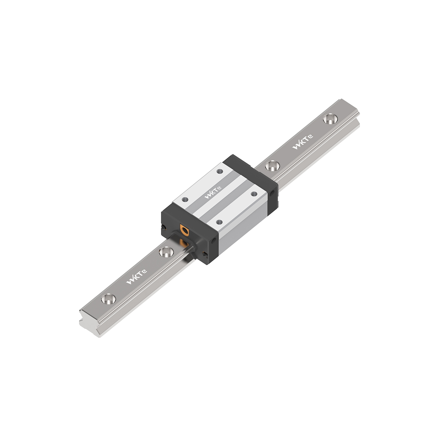
Specifying components for a Z-axis requires stricter evaluation than horizontal systems. You must carefully assess preload, bearing type, and lubrication methods.
Evaluating carriage preload options is your first critical step. Preload eliminates internal clearance between the rolling elements and the raceway. Manufacturers offer different preload classes. These generally include clearance, light, medium, and heavy. Vertical applications typically require medium to heavy preload. A heavier preload maximizes rigidity. It directly counteracts the moment forces generated by cantilevered loads. If you use a clearance or light preload class vertically, the carriage will sag slightly. This sagging amplifies vibration during travel.
Next, you must decide between ball and roller bearings. Roller guides offer higher rigidity. They utilize cylindrical rollers instead of spherical balls. This creates line contact rather than point contact. Line contact distributes heavy loads over a larger surface area. This makes roller guides superior for heavy-duty vertical CNC machines or industrial lifting applications. Ball guides remain sufficient for lighter, high-speed vertical tasks. They work well in automated packaging systems or 3D printing Z-axes. You must strictly respect their moment load ratings to ensure longevity.
Lubrication retention represents a massive hurdle in vertical setups. We call this the gravity problem. Standard oil or grease tends to pool at the bottom of the rail. Over time, the top sections of the rail run dry. Dry raceways cause immediate metal-on-metal friction.
You must evaluate components specifically for vertical lubrication. Look for bearing blocks featuring integrated lubrication units. Many modern blocks use oil-impregnated resin pads. These pads maintain continuous contact with the raceway. They deposit a micro-film of oil during every stroke. Alternatively, you can specify high-viscosity grease. Combine this thick grease with tightly sealed end-caps on the carriage. The tight seals physically scrape and retain the grease inside the block, preventing gravity from draining it.
Bearing Type |
Contact Profile |
Ideal Vertical Application |
Rigidity Level |
|---|---|---|---|
Standard Ball Guide |
Point Contact |
Packaging, Light Automation, 3D Printing |
Moderate (Requires specific preload) |
Cylindrical Roller Guide |
Line Contact |
CNC Machining, Industrial Lifts, Heavy Tooling |
Very High (Superior moment resistance) |
Gravity makes vertical systems inherently dangerous during power loss. Horizontal systems simply coast to a safe stop when power fails. Vertical carriages suffer from the risk of back-driving and free-fall. If the drive mechanism loses power, the payload mass will forcefully drive the carriage downward.
Back-driving occurs easily in highly efficient systems. For example, ballscrews have very little internal friction. Without motor torque holding the screw in place, a heavy vertical load will spin the screw backward. This results in an uncontrolled free-fall. This endangers operators and destroys expensive equipment.
You must integrate specific safety features into any Z-axis design. Pneumatic or electromagnetic brakes are absolutely essential. They hold the carriage firmly in place during emergency stops. They also engage immediately during unexpected power outages. Electromagnetic brakes typically mount directly to the servo or stepper motor. When power drops, the brake defaults to a clamped, locked position.
Counterweights and gas springs offer another layer of safety and efficiency. A counterweight physically balances the mass of your payload. It acts over a pulley system. Gas springs provide a similar upward pushing force without the bulk of heavy iron weights. Both methods drastically reduce the continuous holding torque required by the drive motor.
Reducing holding torque improves system energy efficiency. It also prevents extreme thermal buildup in stepper and servo motors. Motors forced to hold heavy vertical loads continuously will overheat rapidly. Counterbalancing eliminates this thermal stress.
Redundancy planning separates amateur designs from industrial-grade engineering. Never rely solely on the motor holding torque for vertical load safety. Motors can fail. Cables can sever. Always pair a braked motor with a secondary fail-safe, such as a rail-clamping mechanism or a perfectly tuned counterweight system.
Vertical rail installation demands extreme precision. Small errors that horizontal systems might tolerate will cause severe issues in a Z-axis.
Misalignment and binding rank as the most common installation failures. Vertical rails are highly sensitive to parallelism errors. When you mount dual rails vertically, they must remain perfectly parallel across the entire stroke length. Slight misalignments cause severe binding. Gravity offers no lateral forgiveness. The carriage cannot float or self-adjust.
To solve misalignment, use a master rail and subsidiary rail installation method. First, mount the master rail against a precision-machined reference edge. Dial it in perfectly. Then, leave the subsidiary rail bolts slightly loose. Run the carriage assembly up and down a few times. This allows the subsidiary rail to naturally align itself to the master rail. Finally, tighten the subsidiary rail bolts systematically.
Improper fastener torque presents another major risk. Vertical mounting puts mounting bolts in sheer tension. The entire weight of the system tries to slide the rails downward, slicing across the bolts. Standard installations often rely purely on bolt friction to hold rails in place. This is dangerous vertically.
You must adhere strictly to manufacturer torque specs. Furthermore, you should consider using locating pins, also known as dowel pins. Drill and ream dowel holes through the rail and into the machine frame. The steel dowel pins will bear the immense shear load. This protects the threaded mounting bolts from snapping under continuous cyclic stress.
Wiper and seal deformation occurs rapidly in vertical environments. Continuous exposure to falling debris degrades top seals faster. Metal chips, wood dust, or plastic shards fall straight down the track. They accumulate directly on the top seal of the carriage block.
Standard single-lip seals will eventually let fine particles through. These particles mix with the grease. They create an abrasive paste that destroys the raceways. To prevent this, always specify double-lip scrapers for the top-facing end of the carriage. Add metallic scraper plates if you operate in environments with hot chips or heavy debris.
Common Pitfall |
Root Cause |
Engineering Solution |
|---|---|---|
Severe Carriage Binding |
Lack of parallelism between dual vertical rails. |
Utilize a master/subsidiary mounting sequence with dialed reference edges. |
Fastener Shearing |
Mounting bolts bearing the entire vertical load mass. |
Install hardened steel dowel pins to absorb shear forces. |
Premature Raceway Wear |
Debris falling into the top carriage seal. |
Specify double-lip rubber seals and metallic scrapers. |
Following a strict specification process ensures long-term reliability. Use this four-step checklist when engineering your next vertical lift or Z-axis mechanism.
Step 1: Calculate the True Load. You must look beyond simple static weight. Factor in the payload weight first. Next, calculate the acceleration and deceleration forces. Rapid vertical stops generate massive momentary G-forces. Finally, measure the distance of the center of gravity from the rail face. This distance creates a lever arm. A long lever arm exponentially increases the pitch moment loads acting on the carriage blocks.
Step 2: Select the Drive Mechanism. Ensure complete compatibility between your Linear Guide Rails and the drive unit. A self-locking drive, like an acme lead screw, naturally resists back-driving. If you require high speeds and choose a ballscrew or belt drive, you must specify a braked servo motor. The rail supports the load path, but the drive mechanism dictates safety.
Step 3: Define the Duty Cycle. Analyze how often and how fast the system moves. High-speed vertical oscillation requires entirely different thermal and lubrication considerations than a slow, heavy lifting application. High-speed oscillation flings oil away from the ball circuits. Slower, heavy lifts squeeze grease out of the raceways through sheer pressure. Match your lubrication delivery system to the duty cycle.
Step 4: Consult the Manufacturer’s Nomogram. Never use standard horizontal capacity charts for vertical applications. Cross-reference your calculated equivalent load against the manufacturer's specific charts for vertical mounting. Vertical nomograms account for uneven load distribution across the ball circuits. They provide accurate L10 life expectancies for Z-axis configurations.
Next Action: Contact a qualified application engineer. Provide them with your required stroke length, maximum payload, speed profile, and duty cycle. Have them validate your selected part numbers to ensure complete safety and optimal performance.
Standard motion components are fully capable of vertical use, provided the design accommodates the harsh realities of gravity, moment loads, and lubrication migration. You cannot simply turn a horizontal system sideways and expect long-term reliability. Careful calculation of axial forces ensures the ball circuits survive continuous downward stress.
We strongly recommend evaluating your entire safety ecosystem. Properly matching the rail profile, preload levels, and integrated fail-safes to your specific Z-axis requirements prevents budget overruns. More importantly, it prevents severe operational hazards caused by free-falling loads. Do not over-spec blindly, but never under-spec safety.
Take action before finalizing your machine blueprints. Request a comprehensive technical consultation from your component supplier. Download a dedicated vertical-load sizing calculator to verify your application's parameters and ensure your moments and loads remain within safe operational limits.
A: Yes. Generally, a higher viscosity grease like NLGI Grade 2 is required. Standard thin oils will pool at the bottom of the track due to gravity. Alternatively, utilizing a system with continuous capillary lubrication blocks is highly recommended to prevent gravity from pulling the lubricant out of the critical raceways.
A: It is highly discouraged unless your payload is perfectly balanced directly over the carriage center. Single rails struggle immensely with the pitch and roll moments typical of vertical cantilevered loads. Designing with dual rails spaced adequately apart is standard industry practice for Z-axis stability.
A: The linear guide rail itself does not hold the load in place. You must integrate a mechanical or electromagnetic holding brake directly on the drive motor. Alternatively, you can install a pneumatic or hydraulic rail-clamping mechanism directly onto the guide rail block to lock it securely during power loss.


